
Service Manual

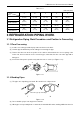
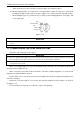
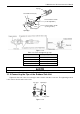
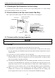
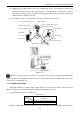
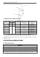
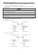
Table Of Contents
- 目录
- 第一部分 产品篇
- 第二部分 控制篇
- CONTROL
- 1 OPERATION FLOWCHART
- 2 WIRELESS REMOTE CONTROLLER
- 3 WIRED CONTROLLER
- 4 OPERATION INSTRUCTION OF SPECIAL FUNCTIONS
- 4.1 Setting of Filter Clean Reminder Function
- 4.2 Low Temperature Drying Function
- 4.3 Lock Function
- 4.4 Memory Function
- 4.5 Door Control Function/Human Sensitive Function
- 4.6 Switch between Fahrenheit and Centigrade
- 4.7 Enquiry of Ambient Temperature
- 4.8 Enquiry of Historical Malfunction
- 4.9 Debugging Function
- 4.9.1 Setting ambient temperature sensor (dual ambient temperature sensors function)
- 4.9.2 Selecting three speeds in high speed and three speeds in low speed of indoor fan motor
- 4.9.3 Displaying setting of freeze protection error code
- 4.9.4 Setting refrigerant lacking protection function
- 4.9.5 Selecting blowing residual heating of indoor unit
- 4.9.6 Mode selecting of compressor electric heating belt
- 4.9.7 Selecting low-power consumption mode
- 4.9.8 Selecting door control function
- 4.9.9 Selecting human sensitive function
- 4.9.10 Selecting long-distance monitoring or centralized controller
- 4.9.11 Selecting fan mode of indoor fan motor
- 4.9.12 Selecting compensation of temperature sensor at air return
- 5 INSTALLATION OF WIRED CONTROLLER
- 6 TROUBLESHOOTING
- 7 CENTRALIZED CONTROLLER
- 7.1 Smart Zone Controller
- 7.2 Additional Special Functions
- 7.2.1 Door control function
- 7.2.2 Human sensitive function
- 7.2.3 MODBUS interface
- 7.2.4 Connect to interface of centralized controller:
- 7.2.5 Light board control:
- 7.2.6 Malfunction output of relay:
- 7.2.7 Reserved fresh air valve interface for duct type unit
- 7.2.8 Interface of anion generator
- 7.2.9 Chassis electric heating belt of outdoor unit is optional
- CONTROL
- 第三部分 安装篇
- INSTALLATION
- 1 INDOOR UNIT INSTALLATION
- 1.1 Installation of Duct Type
- 1.2 Installation of Floor Ceiling Type
- 1.3 Installation of Cassette Type
- 1.3.1 Before Installation
- 1.3.2 Installation Site
- 1.3.3 Installing the Main Body Unit
- 1.3.4 Installing the Suspension Bolts
- 1.3.5 Leveling
- 1.3.6 The Panel Installation
- 1.3.7 Dimension Data
- 1.3.8 Installation of Drain Piping
- 1.3.9 Installing the Drain Pipes
- 1.3.10 Precautions When Doing Riser Piping Work
- 1.3.11 Testing of Drain Piping
- 2 OUTDOOR UNIT INSTALLATION
- 3 REFRIGERATION PIPING WORK
- 3.1 Refrigeration Piping Work Procedures and Caution in Connecting
- 3.2 Specification of Connection Pipe
- 4 ELECTRIC WIRING WORK
- 1 INDOOR UNIT INSTALLATION
- INSTALLATION
- 第四部分 维护篇(上)4.1~4.3
- 第四部分 维护篇(中)4.4拆装
- 第四部分 维护篇(下)4.5爆炸图及清单

U-Match Series DC Inverter Service Manual
81
stretch them any more. Do not bend or stretch the pipes more than three times.
(4) When bending the pipe, do not bend it as is. The pipe will be collapsed. In this case, cut the heat
insulating pipe with a sharp cutter as shown in Figure 3-3-3, and bend it after exposing the pipe.
After bending the pipe as you want, be sure to put the heat insulating pipe back on the pipe, and
secure it with tape.
Pipe
Cutter
Cutt line
Heat insulating
pipe
Figure 3-3-3
①. To prevent breaking of the pipe, avoid sharp bends. Bend the pipe with a radius of curvature of 150mm (5-7/8inch)
or over.
②. If the pipe is bent repeatedly at the same place, it will break.
3.1.3 Connecting the Pipe at the Indoor Unit Side
Detach the caps and plugs from the pipes.
①. Be sure to apply the pipe against the port on the indoor unit correctly. If the centering is improper, the flare nut
cannot be tightened smoothly. If the flare nut is forced to turn, the threads will be damaged.
②. Do not remove the flare nut until the connection pipe is to be connected so as to prevent dust and impurities from
coming into the pipe system.
When connecting the pipe to the unit or removing it from the unit, please do use both the spanner and
the torque wrench (Figure 3-3-4).
When connecting, smear both inside and outside of the flare nut with refrigeration oil, screw it hand
tight and then tighten it with the spanner.
Refer to Table 3-3-1 to check if the wrench has been tightened properly (too tight would mangle the nut
and lead to leakage).
Examine the connection pipe to see if it leaks, then take the treatment of heat insulation, as shown in
the Figure 3-3-4.
Use the medium-sized sponge to insulate the coupler of the gas pipe.