
Service Manual

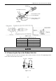
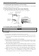
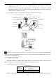
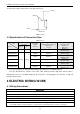
Table Of Contents
- 目录
- 第一部分 产品篇
- 第二部分 控制篇
- CONTROL
- 1 OPERATION FLOWCHART
- 2 WIRELESS REMOTE CONTROLLER
- 3 WIRED CONTROLLER
- 4 OPERATION INSTRUCTION OF SPECIAL FUNCTIONS
- 4.1 Setting of Filter Clean Reminder Function
- 4.2 Low Temperature Drying Function
- 4.3 Lock Function
- 4.4 Memory Function
- 4.5 Door Control Function/Human Sensitive Function
- 4.6 Switch between Fahrenheit and Centigrade
- 4.7 Enquiry of Ambient Temperature
- 4.8 Enquiry of Historical Malfunction
- 4.9 Debugging Function
- 4.9.1 Setting ambient temperature sensor (dual ambient temperature sensors function)
- 4.9.2 Selecting three speeds in high speed and three speeds in low speed of indoor fan motor
- 4.9.3 Displaying setting of freeze protection error code
- 4.9.4 Setting refrigerant lacking protection function
- 4.9.5 Selecting blowing residual heating of indoor unit
- 4.9.6 Mode selecting of compressor electric heating belt
- 4.9.7 Selecting low-power consumption mode
- 4.9.8 Selecting door control function
- 4.9.9 Selecting human sensitive function
- 4.9.10 Selecting long-distance monitoring or centralized controller
- 4.9.11 Selecting fan mode of indoor fan motor
- 4.9.12 Selecting compensation of temperature sensor at air return
- 5 INSTALLATION OF WIRED CONTROLLER
- 6 TROUBLESHOOTING
- 7 CENTRALIZED CONTROLLER
- 7.1 Smart Zone Controller
- 7.2 Additional Special Functions
- 7.2.1 Door control function
- 7.2.2 Human sensitive function
- 7.2.3 MODBUS interface
- 7.2.4 Connect to interface of centralized controller:
- 7.2.5 Light board control:
- 7.2.6 Malfunction output of relay:
- 7.2.7 Reserved fresh air valve interface for duct type unit
- 7.2.8 Interface of anion generator
- 7.2.9 Chassis electric heating belt of outdoor unit is optional
- CONTROL
- 第三部分 安装篇
- INSTALLATION
- 1 INDOOR UNIT INSTALLATION
- 1.1 Installation of Duct Type
- 1.2 Installation of Floor Ceiling Type
- 1.3 Installation of Cassette Type
- 1.3.1 Before Installation
- 1.3.2 Installation Site
- 1.3.3 Installing the Main Body Unit
- 1.3.4 Installing the Suspension Bolts
- 1.3.5 Leveling
- 1.3.6 The Panel Installation
- 1.3.7 Dimension Data
- 1.3.8 Installation of Drain Piping
- 1.3.9 Installing the Drain Pipes
- 1.3.10 Precautions When Doing Riser Piping Work
- 1.3.11 Testing of Drain Piping
- 2 OUTDOOR UNIT INSTALLATION
- 3 REFRIGERATION PIPING WORK
- 3.1 Refrigeration Piping Work Procedures and Caution in Connecting
- 3.2 Specification of Connection Pipe
- 4 ELECTRIC WIRING WORK
- 1 INDOOR UNIT INSTALLATION
- INSTALLATION
- 第四部分 维护篇(上)4.1~4.3
- 第四部分 维护篇(中)4.4拆装
- 第四部分 维护篇(下)4.5爆炸图及清单

U-Match Series DC Inverter Service Manual
83
3.1.5 Checking the Pipe Connections for Gas Leaking
For both indoor and outdoor unit side, check the joints for gas leaking by the use of a gas leakage
detector without fail when the pipes are connected.
3.1.6 Heat Insulation on the Pipe Joints (Indoor Side Only)
Stick coupler heat insulation (large and small) to the place where connecting pipes.
Front outlet
Coupler heat
insulation (small)
on the pipe
Liquid pipe
Gas pipe
Reference A
Coupler heat insulation
(large) on the pipe
Heat insulation pipe
Reference A:
Cover this portion with heat
insulating material also without fail
No gap
Figure 3-3-6
3.1.7 Vacuum and Gas Leakage Inspection
Do not purge the air with refrigerants but use a vacuum pump to vacuum the installation! There is no extra refrigerant in the
outdoor unit for air purging!
3.1.7.1 Vacuum
(1) Remove the caps of the liquid valve, gas valve and also the service port.
(2) Connect the hose at the low pressure side of the manifold valve assembly to the service port of
the unit’s gas valve, and meanwhile the gas and liquid valves should be kept closed in case of
refrigerant leak.
(3) Connect the hose used for evacuation to the vacuum pump.
(4) Open the switch at the lower pressure side of the manifold valve assembly and start the vacuum
pump. Meanwhile, the switch at the high pressure side of the manifold valve assembly should be
kept closed, otherwise evacuation would fail.
(5) The evacuation duration depends on the unit’s capacity, generally, 20 minutes for the 18k units,
30 minutes for the 24k/30k/36k units, 45 minutes for the 42k/48k units. And verify if the pressure
gauge at the low pressure side of the manifold valve assembly reads -1.0MPa (145psig), if not, it
indicates there is leak somewhere. Then, close the switch fully and then stop the vacuum pump.
(6) Wait for some time to see if the system pressure can remain unchanged, 3 minutes for the
18k/24k units, 10 minutes for the 30k/36k/42k/48k units. During this time, the reading of the
pressure gauge at the low pressure side can not be larger than 0.005MPa (0.72psig).