
Service Manual
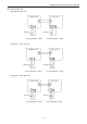
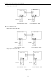
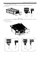
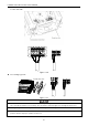

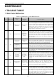
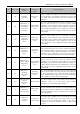
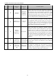
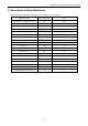
Table Of Contents
- 目录
- 第一部分 产品篇
- 第二部分 控制篇
- CONTROL
- 1 OPERATION FLOWCHART
- 2 WIRELESS REMOTE CONTROLLER
- 3 WIRED CONTROLLER
- 4 OPERATION INSTRUCTION OF SPECIAL FUNCTIONS
- 4.1 Setting of Filter Clean Reminder Function
- 4.2 Low Temperature Drying Function
- 4.3 Lock Function
- 4.4 Memory Function
- 4.5 Door Control Function/Human Sensitive Function
- 4.6 Switch between Fahrenheit and Centigrade
- 4.7 Enquiry of Ambient Temperature
- 4.8 Enquiry of Historical Malfunction
- 4.9 Debugging Function
- 4.9.1 Setting ambient temperature sensor (dual ambient temperature sensors function)
- 4.9.2 Selecting three speeds in high speed and three speeds in low speed of indoor fan motor
- 4.9.3 Displaying setting of freeze protection error code
- 4.9.4 Setting refrigerant lacking protection function
- 4.9.5 Selecting blowing residual heating of indoor unit
- 4.9.6 Mode selecting of compressor electric heating belt
- 4.9.7 Selecting low-power consumption mode
- 4.9.8 Selecting door control function
- 4.9.9 Selecting human sensitive function
- 4.9.10 Selecting long-distance monitoring or centralized controller
- 4.9.11 Selecting fan mode of indoor fan motor
- 4.9.12 Selecting compensation of temperature sensor at air return
- 5 INSTALLATION OF WIRED CONTROLLER
- 6 TROUBLESHOOTING
- 7 CENTRALIZED CONTROLLER
- 7.1 Smart Zone Controller
- 7.2 Additional Special Functions
- 7.2.1 Door control function
- 7.2.2 Human sensitive function
- 7.2.3 MODBUS interface
- 7.2.4 Connect to interface of centralized controller:
- 7.2.5 Light board control:
- 7.2.6 Malfunction output of relay:
- 7.2.7 Reserved fresh air valve interface for duct type unit
- 7.2.8 Interface of anion generator
- 7.2.9 Chassis electric heating belt of outdoor unit is optional
- CONTROL
- 第三部分 安装篇
- INSTALLATION
- 1 INDOOR UNIT INSTALLATION
- 1.1 Installation of Duct Type
- 1.2 Installation of Floor Ceiling Type
- 1.3 Installation of Cassette Type
- 1.3.1 Before Installation
- 1.3.2 Installation Site
- 1.3.3 Installing the Main Body Unit
- 1.3.4 Installing the Suspension Bolts
- 1.3.5 Leveling
- 1.3.6 The Panel Installation
- 1.3.7 Dimension Data
- 1.3.8 Installation of Drain Piping
- 1.3.9 Installing the Drain Pipes
- 1.3.10 Precautions When Doing Riser Piping Work
- 1.3.11 Testing of Drain Piping
- 2 OUTDOOR UNIT INSTALLATION
- 3 REFRIGERATION PIPING WORK
- 3.1 Refrigeration Piping Work Procedures and Caution in Connecting
- 3.2 Specification of Connection Pipe
- 4 ELECTRIC WIRING WORK
- 1 INDOOR UNIT INSTALLATION
- INSTALLATION
- 第四部分 维护篇(上)4.1~4.3
- 第四部分 维护篇(中)4.4拆装
- 第四部分 维护篇(下)4.5爆炸图及清单

U-Match Series DC Inverter Service Manual
95
MAINTENANCE
1 TROUBLE TABLE
1.1 Main Control Malfunction
Table 4-1-1 Fault Display on Indoor Wired Controller
No.
Error code
Malfunction
name
Origin of
malfunction
signal
Control description
1
E1
High pressure
protection
High pressure
switch
When outdoor unit detects the high pressure switch is cut off for
3s successively, high pressure protection will occur. All the loads
(except the 4-way valve in heating mode) will be switched off. In
this case, all the buttons and remote control signals except
ON/OFF button will be disabled and cannot be recovered
automatically. Switch off the unit or re-energize the unit after
cutting off power to eliminate this protection.
2
E2
Freeze protection
Indoor
evaporator
temperature
sensor
If detecting that the evaporator temperature is lower than
protective temp. value after the unit has been running for a
period of time under cooling or dry mode, the unit will report this
fault, in which case the compressor and outdoor fan motor will be
stopped. The unit will not run until evaporator temperature is
higher than the protective temp. value and the compressor is
stopped for 3min.
3
E3
Low pressure
protection
Low pressure
switch
If it is detected within 30s successively that the low-pressure
switch is cut off under ON or standby state, the unit will report low
pressure protection. If the fault occurs successively 3 times
within 30min, the unit cannot be recovered automatically.
Refrigerant
lacking protection
If the unit reports system refrigerant lacking within 10min after
turning on the unit, the unit will stop operation. If the fault occurs
successively 3 times, the unit cannot be recovered automatically.
Refrigerant
recycling mode
If enter refrigerant recycling mode through special operation, E3
will be displayed. After exiting refrigerant recycling mode, the
code will disappear.
4
E4
Compressor high
discharge
temperature
protection
Compressor
discharge
temperature is
high
If outdoor unit detects that the discharge temperature is higher
than protective temp. value, the unit will report high discharge
temperature protection. If the protection occurs over 6 times, the
unit cannot be recovered automatically. Switch off the unit or
re-energize the unit after cutting off power to eliminate this
protection.
5
E6
Communication
malfunction
Communication
between indoor
and outdoor main
board
If the outdoor unit does not receive data from indoor unit,
communication malfunction will be reported. If there is
communication abnormity between display board and indoor unit,
communication malfunction will be reported too.
6
E8
Malfunction of
indoor fan motor
Indoor fan motor
If the indoor unit does not receive signal from indoor fan motor for
30s successively when the fan motor is operating, indoor fan
motor malfunction will be reported. In this case, the unit can
automatically resume operation after stopping. If the malfunction
occurs 6 times within one hour, the unit cannot be recovered
automatically. Switch off the unit or re-energize the unit after
cutting off power to eliminate this malfunction.