SLIM CONCEALED DUCT AIR CONDITIONING & HEATING SYSTEM INSTALLATION MANUAL Models: Indoor Unit UMAT18HP230V1AD UMAT24HP230V1AD UMAT30HP230V1AD UMAT36HP230V1AD UMAT42HP230V1AD UMAT48HP230V1AD Outdoor Unit UMAT18HP230V1AO UMAT24HP230V1AO UMAT30HP230V1AO UMAT36HP230V1AO UMAT42HP230V1AO UMAT48HP230V1AO
Thank you for choosing a Slim Concealed Duct unit for your customer. Please read this installation manual carefully before installing and starting up the U-Match System. Take a moment to fill out the product and installation form on the back cover. Retain both the manual and installation record for future reference. Table of Contents Safety Precautions . . . . . . . . . . . . . . . . . . . . . . . . . . . . . . . . . . . . . . . . . . . . 2 Nomenclature . . . . . . . . . . . . . . . . . . . . . . . . . .
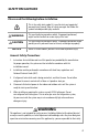
SAFETY PRECAUTIONS Please read the following before installation. This is the safety alert symbol. It is used to alert you to potential personal injury hazards. Obey all safety messages that follow this symbol to avoid possible injury or death. WARNING This mark indicates procedures which, if improperly performed, might lead to the death or serious injury of the user.
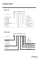
NOMENCLATURE Indoor unit Example: UMAT18HP230V1AD UMAT 18 HP 230V 1 A D Series Designation Product Type S - System O - Outdoor Units H - Indoor High Wall D - Indoor Duct C - Indoor Cassette F - Indoor Floor/Ceiling UMAT – U-Match Series Cooling Capacity 18 - 18,000 BtuH 24 - 24,000 BtuH 30 - 30,000 BtuH 36 - 36,000 BtuH 42 - 42,000 BtuH 48 - 48,000 BtuH Revision Level Style/Color Designation Model Type AC - Cooling Only HP - Heat Pump HC - Heat/Cool Electrical Rating 230V - 208/230V 60Hz 1PH 115V -
SYSTEM REQUIREMENTS REFRIGERANT LINE LENGTHS ft (m) PIPE SIZE in (mm) Unit Size (BtuH) Liquid Line 18,000 24,000 30,000 36,000 42,000 48,000 1/4 (6) 3/8 (10) 3/8 (10) 3/8 (10) 3/8 (10) 3/8 (10) Suction/Gas Line Min Line Length 1/2 (12) 5/8 (15) 5/8 (15) 5/8 (15) 5/8 (15) 5/8 (15) 10 (3) 10 (3) 10 (3) 10 (3) 10 (3) 10 (3) Max. Pre-Charge Max Line Max Elevation Line Length Length (ID over OD) 25(7.5) 25(7.5) 25(7.5) 25(7.5) 25(7.5) 25(7.
SUGGESTED TOOLS • Standard Wrench • Adjustable/Crescent Wrench • Torque Wrench • Hex Keys or Allen Wrenches • Drill & Drill Bits • Hole Saw • Pipe Cutter • Screw drivers (Phillips & Flat blade) • Manifold and Gauges • Level • R410A Flaring Tool • Clamp on Amp Meter • Vacuum Pump • Safety Glasses • Work Gloves • Refrigerant Scale • Micron Gauge 5
SYSTEM SCHEMATIC Indoor Unit 1 Air outlet 2 System Components* 1.Indoor Power Supply 2.Electric Box 3.Communication Cable 4.XK60 Wired Programmable Controller 5.Communication Cable 6.Front Panel 7.Service Cover 8.Liquid Pipe 9.Gas Pipe 10.Drain Hose 11.Outdoor Power Supply 3 4 5 Air inlet * Not all components included with equipment purchase.
STANDARD PARTS Indoor Unit Accessories No.
INSTALLATION SITE INSTRUCTIONS Indoor Unit WARNING The unit must be installed in a location which can withstand twice the weight of the unit. Inadequate building support at the installation location may result in serious property damage and injuries. Review the installation location with the customer as follows: 1. Ceiling is strong enough to support twice the weight of the unit. 2. Ductwork can easily be installed using the shortest amount of duct. 3. Location allows easy installation of drain pipe. 4.
INSTALLATION SITE INSTRUCTIONS Outdoor Unit WARNING The unit should be installed level on a pad that can support twice the weight of the unit. If the outdoor unit will be exposed to strong winds, it must be adequately secured. CAUTION Do not install the unit at a location where the distance exceeds the maximum length indicated in the table. The maximum length of the connection pipe is listed in the System Requirements section. 1.
INDOOR UNIT INSTALLATION For the units: 18K INDOOR UNIT DIMENSIONS in (mm) Model UMAT18HP230V1AD A B C D E F G H I J 37-1/4 (945) 24-3/8 (618) 29 (738) 35-1/8 (892) 40-7/8 (1037) 28-3/8 (721) 29 (738) 4-7/8 (125) 8 (203) 10-1/2 (266) (Approx) For the units: 24-42K INDOOR UNIT DIMENSIONS in (mm) Model A B C D E F G H I J UMAT24HP230V1AD UMAT30HP230V1AD 43-3/8 (1101) 20-3/8 (517) 32-1/4 (820) 45-5/8 (1159) 50-3/8 (1279) 22 (558) 39-1/2 (1002) 6-1/4 (160) 9-1/4 (235
INDOOR UNIT INSTALLATION For the units: 48K INDOOR UNIT DIMENSIONS in (mm) Model UMAT48HP230V1AD A B C D E F G H I J 43-3/8 (1101) 25-3/8 (646) 33-1/2 (852) 45-1/4 (1150) 52-3/4 (1340) 29-1/2 (750) 37-1/2 (953) 7-1/2 (190) 12-1/2 (316) 13-3/4 (350) 11
INDOOR UNIT INSTALLATION Mounting Indoor Unit It is critical to properly secure the indoor unit to a stable and rigid structure that can support twice its weight for safety and product reliability. Select the proper size suspension bolts or anchoring devices (field supplied) to support twice the weight of the unit. 1. 2. 3. 4. 5. 6 7. 8. 9. Locate a structure strong enough to support twice the weight of the unit.
OUTDOOR UNIT INSTALLATION WARNING The unit should be located with the unit support feet firmly on the equipment pad. If the outdoor unit is exposed to wind, it must be properly secured.
OUTDOOR UNIT INSTALLATION Condensate Drainage of the Outdoor Unit The outdoor unit should be installed with a drain pipe to drain condensate water during the heating mode. 1. Insert the drain joint (included) into the selected hole located on the bottom of the base pan and then connect the drain hose (field supplied) to the drain joint. 2. All other holes must be sealed with plugs (included) to avoid water leaks, except for the drain pipe mounting hole. 3.
PIPING INSTALLATION Refrigerant Piping Drill Hole in Wall Indoor 1. Locate and mark proper location for the wall hole. 2. Cut the 2 3/4” wall hole with a 5° to 10° downward slant to the outdoors. Outdoor Wall Hole Sleeve Seal Hole 3. Insert a wall sleeve (field supplied) into hole to to prevent damage to refrigerant pipes, insulation, condensate drain hose and wiring. Hole Size Wall Hole Diagram 4.
PIPING INSTALLATION Indoor Unit Pipe Connections 1. Feed refrigerant pipes, drain hose and interconnecting wires assembly through wall hole from outdoor to the indoor unit. 2. Pull the piping assembly to the unit. Carefully bend refrigerant pipes to meet indoor unit connection ports. Use proper tools to avoid kinks. Copper Oil applied (to reduce friction piping 3. Add a small amount of refrigerant oil to with the flare nut) both ends of the flare fittings. 4.
PIPING INSTALLATION Outdoor Unit Pipe Connections 1. Remove service valve cover (if provided) to access the service valves and refrigerant ports. Service Service Valve Valve Cover Cover 2. Carefully bend and adjust length of refrigerant pipes to meet outdoor unit service valve connections with proper tools to avoid kinks. Gas pipe Liquid pipe Pipe coupling 3. Add a small amount of refrigerant oil to both ends of the flare fittings. or 3-way valve 4.
PIPING INSTALLATION Indoor Condensate Drain Piping WARNING Observe all local sanitary codes when installing condensate drains. See Table below for Condensate Drainage port size. Capacity Size (BtuH) 18,000 24,000-48,000 Drain Connection Size (OD) 1-1/8 (30) 3/4 (20) Pitch the condensate drain pipe at a gradual 2.5% pitch (Example: ¼-in drop over a 10-in length) without obstructions. Use pipe hanger/brackets to support the condensate drain pipe from dropping.
PIPING INSTALLATION Vertical Lift Drainage System (Internal Condensate Pump) If a gradual pitch from the drainage port is not obtainable, the indoor unit has a lift condensate drain pump *with limited head or lift.The condensate drain pipe may have a vertical height of 33 in. maximum above the unit drainage port within the first 12-in as long as the remaining condensate drain pipe gradually descends from that point and is aligned with drainage port.
DUCTWORK INSTALLATION Design and Layout of Ductwork The ductwork configuration should be based on the conditions of the building and maintenance etc., as shown below.
DUCTWORK INSTALLATION Duct Sizing Suggestions Correct ductwork design is critical to insure proper system performance. The total length of the ductwork is the length of the return air duct plus the supply air duct. It is recommend that the ductwork and register selection should follow ACCA manual D duct design to insure proper velocity and air flow. NOMINAL EXT. STATIC PRESSURE Capacity Size (BtuH) 18K 24K 30K 36K 42K 48K Air Flow Rate (CFM) Ext. Static Pressure (InWg) 585 0.1 820 0.1 820 0.
DUCTWORK INSTALLATION Bottom Return Air Installation (18,000 BtuH Only) The 18,000 BtuH size duct can be converted from a rear to bottom side return. More noise is produced with the bottom return air location than the rear return air, so it is suggested to provide a duct silencer to minimize the noise. The default location of the return air connection is at the rear.
POWER AND WIRING INSTALLATION WARNING 1. Before obtaining access to terminals, all electrical supply circuits must be disconnected. 2. Always use an independent circuit and provide an independent circuit breaker to supply power to the system. 3. Use a circuit breaker with adequate capacity to meet the requirements of the total system. 4. A circuit breaker or fuse should be installed per the National Electric Code (NEC) and local regulations. 5.
POWER AND WIRING INSTALLATION Electric Wiring Between Indoor Unit and Outdoor Unit Typical Wiring Diagram Wired Controller X1 X 2 H1 H2 Single-phase units (18K~48K) Outdoor Air Damper G Power: G Power: Indoor Unit Electrical Wiring Locate and remove the electrical box cover to access wire terminals. Indoor Communication Wiring The recommended communication cable size is a minimum 18/2 AWG stranded bare copper conductors 300V unshielded wire.
POWER AND WIRING INSTALLATION Outdoor Air Damper Wiring (optional) Follow the manufacturer’s instructions for installing and wiring the outdoor air damper. On the indoor unit, locate wire terminals F, C, O for outdoor air damper. Make necessary connections to F (Common), C (Close) and O (Open) terminals. Secure electrical wires inside wire clamp/strain relief. Verify wires are secure, not loose and no external force on wires affects the connections at the terminals.
CONTROLLER INSTALLATION AND SETUP The following is a brief overview of the Wired Programmable Controller installation. See Owner's Manual for more detailed instructions for setup and operation. Preparation for Installation Select a proper location on the wall for mounting the Programmable Controller. Install switch box, if required by code. The maximum wire length between indoor and Programmable Controller is 30-ft.
CONTROLLER INSTALLATION AND SETUP Unit Control Indicators The Slim Duct unit has a basic user interface panel and display. It operates in conjunction with the Programmable Controller. There are two buttons on the panel. A"Cool" button which will force the unit into Cool Mode with a 79° F (26° C) set temperature. And a"Heat" button which will force the unit into heat mode with a 68° F (20° C) set temperature. The dual 7-segment display will display error codes to speed up troubleshooting and repairs.
TESTING AND INSPECTION Pipe Testing Gauge manifold Pressure gauge (low-pressure) Pressure gauge (hi-pressure) Switch (low-pressure) Switch (hi-pressure) Connection pipe (to indoor unit) Connection pipe Cap Liquid valve Gas valve Service pipe Hose Service port Cap Cap Hose Hose with the valve pin Vacuum pump Leak Test Refrigerant lines should be pressurized prior to evacuating system to check for leaks. 1. Connect regulated nitrogen to manifold. Attach hose to service port. 2.
TESTING AND INSPECTION Vacuum Procedure Important: Use a quality Micron Gauge to measure and validate the proper system vacuum level achieved. Do not rely on the scale of a“bourbon tube”type gauge set to validate the depth and quality of the vacuum. 1. Remove the caps of the liquid valve, gas valve and service port. 2. Connect gauge manifold and micron gauge to the service ports provided at the liquid and suction service valves. 3. Connect a vacuum pump to the manifold gauge. 4.
TESTING AND INSPECTION Start-up Checklist □ Turn on main power to indoor and outdoor units. • Verify the system is not displaying an error code on the indoor unit or Wired Programmable Controller display. □ Press the ON button on the Wired Programmable Controller. • Verify the Wired Programmable Controller Controller display turns ON. □ Press the Mode button to Cooling. Adjust the room setpoint to bring the system on in cooling mode. The system should start cooling mode within 3-5 minutes.
TROUBLESHOOTING PROBLEM CAUSE/SOLUTION System does not restart. Cause: The system has a built-in three-minute delay to prevent short and/or rapid cycling of the compressor. Solution: Wait three minutes for the protection delay to expire. Indoor unit emits unpleasant odor when started Cause: Typically unpleasant odors are the result of mold or mildew forming on the coil surfaces or the air filter. Solution: Wash indoor air filter in warm water with mild cleaner.
TROUBLESHOOTING PROBLEM CAUSE/SOLUTION Water leakage from the outdoor unit. Cause: It is normal for the outdoor unit to generate condensate water in the reverse cycle heating and defrost mode. Solution: This is normal. No action is required. Water leaking from the indoor unit into the room. Cause: While it is normal for the system to generate condensate water in cooling mode, it is designed to drain this water via a condensate drain system to a safe location.
DIAGNOSTIC CODES The U-Match System has on board diagnostics. The indoor unit and Wired Programmable Controller will display error codes. The following is a summary of the codes with explanation: Error Codes No. 1 2 3 Error Code E1 E2 E3 4 E4 5 E6 Malfunction Name Origin of Malfunction Description If outdoor unit detects the high pressure switch is cut off for 3-sec successively, high pressure protection will occur. All the loads (except the 4-way valve in heating mode) will be switched off.
DIAGNOSTIC CODES Error Codes No. 6 7 8 9 10 Error Code Malfunction Name Origin of Malfunction Indoor Fan Motor E8 Description If the indoor unit does not receive signal from indoor fan motor for 30-sec successively when the fan motor is operating, indoor fan motor malfunction will be reported. In this case, the unit can automatically resume operation after stopping. If the malfunction occurs 6 times within one hour, the unit cannot be recovered automatically.
DIAGNOSTIC CODES Error Codes No.
DIAGNOSTIC CODES Error Codes No. 17 18 19 20 Error Code Malfunction Name H6 Outdoor Fan Motor Malfunction U7 P6 EE Reversing or 4-way Valve Malfunction Origin of Malfunction Outdoor Fan Motor If outdoor unit does not receive feedback signal from outdoor fan motor for 30-sec successively when the fan motor is operating, an outdoor fan motor malfunction will be reported. In this case, the unit can automatically resume operation after stopping.
CARE AND CLEANING Routine Maintenance NOTE: Filters should be installed before operating the air conditioner, otherwise dirt or dust could enter the unit. Do not remove the air filter except for cleaning. Cleaning The air filter should be cleaned every 90 days. Cleaning frequency should be increased if the unit is installed in a room where there is an abnormal amount of dirt and dust. 1. Remove the air filter from the duct. 2. Clean the air filter.
GREE ELECTRIC APPLIANCES, INC. www.greecomfort.com PRODUCT & INSTALLATION RECORD For your convenience, please record the model and serial numbers of your new equipment in the spaces provided. This information, along with the installation data and dealer contact information, will be helpful should your system require maintenance or service. UNIT INFORMATION Outdoor Unit: Model No. Serial No. Indoor Unit: Model No. Serial No.