
Service Manual

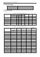
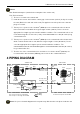
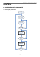
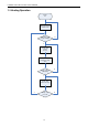
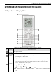

Table Of Contents
- 目录
- 第一部分 产品篇
- 第二部分 控制篇
- CONTROL
- 1 OPERATION FLOWCHART
- 2 WIRELESS REMOTE CONTROLLER
- 3 WIRED CONTROLLER
- 4 OPERATION INSTRUCTION OF SPECIAL FUNCTIONS
- 4.1 Setting of Filter Clean Reminder Function
- 4.2 Low Temperature Drying Function
- 4.3 Lock Function
- 4.4 Memory Function
- 4.5 Door Control Function/Human Sensitive Function
- 4.6 Switch between Fahrenheit and Centigrade
- 4.7 Enquiry of Ambient Temperature
- 4.8 Enquiry of Historical Malfunction
- 4.9 Debugging Function
- 4.9.1 Setting ambient temperature sensor (dual ambient temperature sensors function)
- 4.9.2 Selecting three speeds in high speed and three speeds in low speed of indoor fan motor
- 4.9.3 Displaying setting of freeze protection error code
- 4.9.4 Setting refrigerant lacking protection function
- 4.9.5 Selecting blowing residual heating of indoor unit
- 4.9.6 Mode selecting of compressor electric heating belt
- 4.9.7 Selecting low-power consumption mode
- 4.9.8 Selecting door control function
- 4.9.9 Selecting human sensitive function
- 4.9.10 Selecting long-distance monitoring or centralized controller
- 4.9.11 Selecting fan mode of indoor fan motor
- 4.9.12 Selecting compensation of temperature sensor at air return
- 5 INSTALLATION OF WIRED CONTROLLER
- 6 TROUBLESHOOTING
- 7 CENTRALIZED CONTROLLER
- 7.1 Smart Zone Controller
- 7.2 Additional Special Functions
- 7.2.1 Door control function
- 7.2.2 Human sensitive function
- 7.2.3 MODBUS interface
- 7.2.4 Connect to interface of centralized controller:
- 7.2.5 Light board control:
- 7.2.6 Malfunction output of relay:
- 7.2.7 Reserved fresh air valve interface for duct type unit
- 7.2.8 Interface of anion generator
- 7.2.9 Chassis electric heating belt of outdoor unit is optional
- CONTROL
- 第三部分 安装篇
- INSTALLATION
- 1 INDOOR UNIT INSTALLATION
- 1.1 Installation of Duct Type
- 1.2 Installation of Floor Ceiling Type
- 1.3 Installation of Cassette Type
- 1.3.1 Before Installation
- 1.3.2 Installation Site
- 1.3.3 Installing the Main Body Unit
- 1.3.4 Installing the Suspension Bolts
- 1.3.5 Leveling
- 1.3.6 The Panel Installation
- 1.3.7 Dimension Data
- 1.3.8 Installation of Drain Piping
- 1.3.9 Installing the Drain Pipes
- 1.3.10 Precautions When Doing Riser Piping Work
- 1.3.11 Testing of Drain Piping
- 2 OUTDOOR UNIT INSTALLATION
- 3 REFRIGERATION PIPING WORK
- 3.1 Refrigeration Piping Work Procedures and Caution in Connecting
- 3.2 Specification of Connection Pipe
- 4 ELECTRIC WIRING WORK
- 1 INDOOR UNIT INSTALLATION
- INSTALLATION
- 第四部分 维护篇(上)4.1~4.3
- 第四部分 维护篇(中)4.4拆装
- 第四部分 维护篇(下)4.5爆炸图及清单

U-Match Series DC Inverter Service Manual
17
- button
Preset temperature can be decreased by pressing this button. Pressing and holding this
button for more than 2 seconds can make the temperature changed quickly until release
this button and then transmit this order. The temperature adjustment is unavailable under
the Auto mode, but the order can be sent by pressing this button. Centigrade setting
range: 16~30; Fahrenheit scale setting range 61~86.
+ button
Preset temperature can be increased by pressing this button. Pressing and holding this
button for more than 2 seconds can make the temperature changed quickly until release
the button and then transmit this order. The temperature adjustment is unavailable under
the Auto mode, but the order can be sent by pressing this button. Centigrade setting
range: 16~30; Fahrenheit scale setting range 61~86.
FAN button
By pressing this button, Auto, Low, Middle, High speed can be circularly selected. After
power on, Auto fan speed is default.
Low speed
Middle speed
High speed
Note: Under the DRY mode, the fan will be kept running at the low speed and the fan speed
isn't adjustable.
SWING
UP/DOWN
button
Press this button to set up the swing angle, which circularly changes as below:
When the guide louver starts to swing up and down, if SWING functions are canceled, the
air guide louver will stop and remains at the current position.
Indicates the guide louver swings up and down among those five directions
(Simplified SWING function applicable for some Fan Coil Units: When the wireless
remote controller is energized initially with the unit under the OFF status, it should be set
by pressing the + button and the SWING button simultaneously, with the symbol
blinking twice. Then, after the unit is turned on, this function can be activated by pressing
the SWING button, with the displayed symbol indicating swing function is on and
without this displayed symbol indicating swing function is off).
CLOCK
button
By pressing this button, the clock is allowed to be set, with blinking, and then press
the +/- button to adjust the clock within 5 seconds. If the +/-button is pressed down
constantly for more than 2 seconds, the clock setting will be increased or decreased 10
minutes every 0.5 seconds. After that, another press on the CLOCK button accepts the
setting. 12:00 is the default, when the wireless remote controller is energized.
TIMER ON
button
When TIMER ON is activated, ON will blink while the symbol will disappear. Within 5
seconds it is allowed to set the ON time by pressing the +/- button. Each press will make
the time increase or decrease one minute. Besides, the time can also be set by pressing
the +/- button constantly. That is, in the early 2.5 seconds, the time will
increase/decrease quickly per single minute, and in the late 2.5, the time will
increase/decrease per ten minutes. After the desired time value is set, press TIENE ON
again to conform the setting within five seconds. After that, another press on TIMER ON
will cancel the setting. Prior to this setting, the clock shall be set to the actual time.