
Service Manual
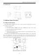
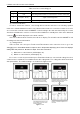
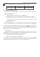
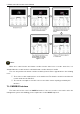
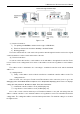
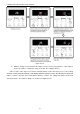

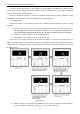

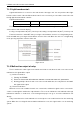
Table Of Contents
- 目录
- 第一部分 产品篇
- 第二部分 控制篇
- CONTROL
- 1 OPERATION FLOWCHART
- 2 WIRELESS REMOTE CONTROLLER
- 3 WIRED CONTROLLER
- 4 OPERATION INSTRUCTION OF SPECIAL FUNCTIONS
- 4.1 Setting of Filter Clean Reminder Function
- 4.2 Low Temperature Drying Function
- 4.3 Lock Function
- 4.4 Memory Function
- 4.5 Door Control Function/Human Sensitive Function
- 4.6 Switch between Fahrenheit and Centigrade
- 4.7 Enquiry of Ambient Temperature
- 4.8 Enquiry of Historical Malfunction
- 4.9 Debugging Function
- 4.9.1 Setting ambient temperature sensor (dual ambient temperature sensors function)
- 4.9.2 Selecting three speeds in high speed and three speeds in low speed of indoor fan motor
- 4.9.3 Displaying setting of freeze protection error code
- 4.9.4 Setting refrigerant lacking protection function
- 4.9.5 Selecting blowing residual heating of indoor unit
- 4.9.6 Mode selecting of compressor electric heating belt
- 4.9.7 Selecting low-power consumption mode
- 4.9.8 Selecting door control function
- 4.9.9 Selecting human sensitive function
- 4.9.10 Selecting long-distance monitoring or centralized controller
- 4.9.11 Selecting fan mode of indoor fan motor
- 4.9.12 Selecting compensation of temperature sensor at air return
- 5 INSTALLATION OF WIRED CONTROLLER
- 6 TROUBLESHOOTING
- 7 CENTRALIZED CONTROLLER
- 7.1 Smart Zone Controller
- 7.2 Additional Special Functions
- 7.2.1 Door control function
- 7.2.2 Human sensitive function
- 7.2.3 MODBUS interface
- 7.2.4 Connect to interface of centralized controller:
- 7.2.5 Light board control:
- 7.2.6 Malfunction output of relay:
- 7.2.7 Reserved fresh air valve interface for duct type unit
- 7.2.8 Interface of anion generator
- 7.2.9 Chassis electric heating belt of outdoor unit is optional
- CONTROL
- 第三部分 安装篇
- INSTALLATION
- 1 INDOOR UNIT INSTALLATION
- 1.1 Installation of Duct Type
- 1.2 Installation of Floor Ceiling Type
- 1.3 Installation of Cassette Type
- 1.3.1 Before Installation
- 1.3.2 Installation Site
- 1.3.3 Installing the Main Body Unit
- 1.3.4 Installing the Suspension Bolts
- 1.3.5 Leveling
- 1.3.6 The Panel Installation
- 1.3.7 Dimension Data
- 1.3.8 Installation of Drain Piping
- 1.3.9 Installing the Drain Pipes
- 1.3.10 Precautions When Doing Riser Piping Work
- 1.3.11 Testing of Drain Piping
- 2 OUTDOOR UNIT INSTALLATION
- 3 REFRIGERATION PIPING WORK
- 3.1 Refrigeration Piping Work Procedures and Caution in Connecting
- 3.2 Specification of Connection Pipe
- 4 ELECTRIC WIRING WORK
- 1 INDOOR UNIT INSTALLATION
- INSTALLATION
- 第四部分 维护篇(上)4.1~4.3
- 第四部分 维护篇(中)4.4拆装
- 第四部分 维护篇(下)4.5爆炸图及清单

U-Match Series DC Inverter Service Manual
47
7.2.5 Light board control:
Light board interface is reserved on the main board of duct type unit. You can purchase Gree light
board to realize control of the unit. When wired control is also connected, you can realize control of the unit
through light board and wired controller.
Light board information:
Name
Product code
Remark
Receiving board Z6L
30260000001
Only for duct type unit
There are two buttons on the light board to control ON/OFF of cooling and heating. There are also
other indicators and nixie tube display.
Cooling: set temperature 26°(79℉), low fan speed; heating: set temperature 20°(68℉), low fan speed
Function instructions: under OFF state, pressing Cool/Heat button can turn on cooling/heating mode.
Under unit ON state, pressing Cool/Heat button can turn off the unit. When the unit is in cooling/heating
mode, pressing any button can turn off the unit.
Figure 2-7-14
7.2.6 Malfunction output of relay:
There is malfunction outlet signal on the main board of indoor unit; when the unit occurs unrecovered
malfunction, this signal will be output.
(1) Interface instruction:
1) Printing: X5, ERROR
2) Electrical characteristic OF malfunction indicator or electric bell: 220V~AC, power≤10W
3) Working principle: when the unit occurs unrecovered malfunction, the relay will suck and 220V
AC signal will be output.
(2) Function instructions:
When the user needs centralized control over several units, malfunction signals can be connected to
control room through this malfunction output interface. The user can indicate the unit malfunction through
malfunction indicator or electric bell, so the management people can go to check the malfunction unit
directly.
If dry contact detection of unit malfunction is needed, please connect this interface into the monitoring
system. When the closed signal is detected when malfunction occurs, this signal can be seen in monitoring
system.