
Service Manual
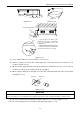
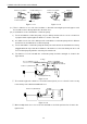
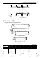
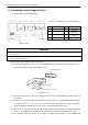
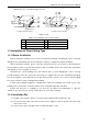
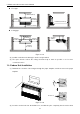
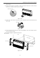
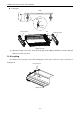
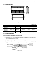
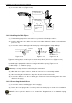
Table Of Contents
- 目录
- 第一部分 产品篇
- 第二部分 控制篇
- CONTROL
- 1 OPERATION FLOWCHART
- 2 WIRELESS REMOTE CONTROLLER
- 3 WIRED CONTROLLER
- 4 OPERATION INSTRUCTION OF SPECIAL FUNCTIONS
- 4.1 Setting of Filter Clean Reminder Function
- 4.2 Low Temperature Drying Function
- 4.3 Lock Function
- 4.4 Memory Function
- 4.5 Door Control Function/Human Sensitive Function
- 4.6 Switch between Fahrenheit and Centigrade
- 4.7 Enquiry of Ambient Temperature
- 4.8 Enquiry of Historical Malfunction
- 4.9 Debugging Function
- 4.9.1 Setting ambient temperature sensor (dual ambient temperature sensors function)
- 4.9.2 Selecting three speeds in high speed and three speeds in low speed of indoor fan motor
- 4.9.3 Displaying setting of freeze protection error code
- 4.9.4 Setting refrigerant lacking protection function
- 4.9.5 Selecting blowing residual heating of indoor unit
- 4.9.6 Mode selecting of compressor electric heating belt
- 4.9.7 Selecting low-power consumption mode
- 4.9.8 Selecting door control function
- 4.9.9 Selecting human sensitive function
- 4.9.10 Selecting long-distance monitoring or centralized controller
- 4.9.11 Selecting fan mode of indoor fan motor
- 4.9.12 Selecting compensation of temperature sensor at air return
- 5 INSTALLATION OF WIRED CONTROLLER
- 6 TROUBLESHOOTING
- 7 CENTRALIZED CONTROLLER
- 7.1 Smart Zone Controller
- 7.2 Additional Special Functions
- 7.2.1 Door control function
- 7.2.2 Human sensitive function
- 7.2.3 MODBUS interface
- 7.2.4 Connect to interface of centralized controller:
- 7.2.5 Light board control:
- 7.2.6 Malfunction output of relay:
- 7.2.7 Reserved fresh air valve interface for duct type unit
- 7.2.8 Interface of anion generator
- 7.2.9 Chassis electric heating belt of outdoor unit is optional
- CONTROL
- 第三部分 安装篇
- INSTALLATION
- 1 INDOOR UNIT INSTALLATION
- 1.1 Installation of Duct Type
- 1.2 Installation of Floor Ceiling Type
- 1.3 Installation of Cassette Type
- 1.3.1 Before Installation
- 1.3.2 Installation Site
- 1.3.3 Installing the Main Body Unit
- 1.3.4 Installing the Suspension Bolts
- 1.3.5 Leveling
- 1.3.6 The Panel Installation
- 1.3.7 Dimension Data
- 1.3.8 Installation of Drain Piping
- 1.3.9 Installing the Drain Pipes
- 1.3.10 Precautions When Doing Riser Piping Work
- 1.3.11 Testing of Drain Piping
- 2 OUTDOOR UNIT INSTALLATION
- 3 REFRIGERATION PIPING WORK
- 3.1 Refrigeration Piping Work Procedures and Caution in Connecting
- 3.2 Specification of Connection Pipe
- 4 ELECTRIC WIRING WORK
- 1 INDOOR UNIT INSTALLATION
- INSTALLATION
- 第四部分 维护篇(上)4.1~4.3
- 第四部分 维护篇(中)4.4拆装
- 第四部分 维护篇(下)4.5爆炸图及清单

U-Match Series DC Inverter Service Manual
67
(4) Connect the drain hose (Figure 3-1-32).
Drain hose must
slope downward.
Allow no trap to
form in the piping
Do not allow end
of hose to touch
water
Figure 3-1-32
1.2.6.2 Installing the Drain Pipes
(1) For determining the position of the drain hose, perform the following procedures.
(2) Insert the drain pipe to the drain outlet of the unit and then tighten the clamp securely with tape
(Figure 3-1-33).
(3) Connect the extension drain pipe to the drain pipe and then tighten the clamp with tape.
1
2
3
1
2
Drain pan
≤4mm(1/8inch)
Seal
Drain hose
Figure 3-1-33 Figure 3-1-34 Figure 3-1-35
Tighten the clamp until the screw head is less than 4mm (1/8inch) from the hose (Figure 3-1-34).
①- Metal clamp ②- Drain hose ③- Grey tape
Insulate the pipe clamp and the drain hose using heat insulation sponge ( Figure 3-1-35).
①- Metal clamp ②- Insulation sponge
Note:
Step 1 to Step 3 have been finished by the manufacturer.
(4) When drain hose requires extension, obtain an extension hose commercially available.
(5) After connecting the local drain hose, tape the slits of the heat insulation tube.
(6) Connect the drain hose to the local drain pipe. Position the inter connecting wire in the same
direction as the piping.
1.2.6.3 Connecting the Drain Hose
(1) Connect the extension auxiliary pipe to the local piping.
(2) Prepare the local piping at the connection point for the drain pipe, as shown in the installation
drawings.
Note:
Be sure to place the drain hose as shown in the diagram below, in a downward sloping
direction.