
Service Manual
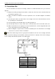
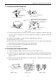

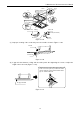
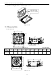
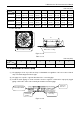
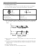
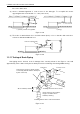
Table Of Contents
- 目录
- 第一部分 产品篇
- 第二部分 控制篇
- CONTROL
- 1 OPERATION FLOWCHART
- 2 WIRELESS REMOTE CONTROLLER
- 3 WIRED CONTROLLER
- 4 OPERATION INSTRUCTION OF SPECIAL FUNCTIONS
- 4.1 Setting of Filter Clean Reminder Function
- 4.2 Low Temperature Drying Function
- 4.3 Lock Function
- 4.4 Memory Function
- 4.5 Door Control Function/Human Sensitive Function
- 4.6 Switch between Fahrenheit and Centigrade
- 4.7 Enquiry of Ambient Temperature
- 4.8 Enquiry of Historical Malfunction
- 4.9 Debugging Function
- 4.9.1 Setting ambient temperature sensor (dual ambient temperature sensors function)
- 4.9.2 Selecting three speeds in high speed and three speeds in low speed of indoor fan motor
- 4.9.3 Displaying setting of freeze protection error code
- 4.9.4 Setting refrigerant lacking protection function
- 4.9.5 Selecting blowing residual heating of indoor unit
- 4.9.6 Mode selecting of compressor electric heating belt
- 4.9.7 Selecting low-power consumption mode
- 4.9.8 Selecting door control function
- 4.9.9 Selecting human sensitive function
- 4.9.10 Selecting long-distance monitoring or centralized controller
- 4.9.11 Selecting fan mode of indoor fan motor
- 4.9.12 Selecting compensation of temperature sensor at air return
- 5 INSTALLATION OF WIRED CONTROLLER
- 6 TROUBLESHOOTING
- 7 CENTRALIZED CONTROLLER
- 7.1 Smart Zone Controller
- 7.2 Additional Special Functions
- 7.2.1 Door control function
- 7.2.2 Human sensitive function
- 7.2.3 MODBUS interface
- 7.2.4 Connect to interface of centralized controller:
- 7.2.5 Light board control:
- 7.2.6 Malfunction output of relay:
- 7.2.7 Reserved fresh air valve interface for duct type unit
- 7.2.8 Interface of anion generator
- 7.2.9 Chassis electric heating belt of outdoor unit is optional
- CONTROL
- 第三部分 安装篇
- INSTALLATION
- 1 INDOOR UNIT INSTALLATION
- 1.1 Installation of Duct Type
- 1.2 Installation of Floor Ceiling Type
- 1.3 Installation of Cassette Type
- 1.3.1 Before Installation
- 1.3.2 Installation Site
- 1.3.3 Installing the Main Body Unit
- 1.3.4 Installing the Suspension Bolts
- 1.3.5 Leveling
- 1.3.6 The Panel Installation
- 1.3.7 Dimension Data
- 1.3.8 Installation of Drain Piping
- 1.3.9 Installing the Drain Pipes
- 1.3.10 Precautions When Doing Riser Piping Work
- 1.3.11 Testing of Drain Piping
- 2 OUTDOOR UNIT INSTALLATION
- 3 REFRIGERATION PIPING WORK
- 3.1 Refrigeration Piping Work Procedures and Caution in Connecting
- 3.2 Specification of Connection Pipe
- 4 ELECTRIC WIRING WORK
- 1 INDOOR UNIT INSTALLATION
- INSTALLATION
- 第四部分 维护篇(上)4.1~4.3
- 第四部分 维护篇(中)4.4拆装
- 第四部分 维护篇(下)4.5爆炸图及清单

U-Match Series DC Inverter Service Manual
76
Indoor unit
Joint
Indoor unit
Indoor unit
H
H/2
Joint
Figure 3-1-52 Figure 3-1-53 Figure 3-1-54
(8) Connection of drainage branch pipe to the standpipe or horizontal pipe of drainage main pipe.
(9) The horizontal pipe cannot be connected to the vertical pipe at a same height. It can be connected
in a manner as shown below:
NO.1: Attach the 3-way connection of the drainage pipe joint as shown in Figure 3-1-55.
NO.2: Attach the drain elbow as shown in Figure 3-1-56.
NO.3: Attach the horizontal pipe as shown in Figure 3-1-57.
3-way connection of
drainage pipe joint
Connection of drain elbow
Connection of horizontal pipe
Figure 3-1-55 Figure 3-1-56 Figure 3-1-57
1.3.10 Precautions When Doing Riser Piping Work
(1) Make sure that heat insulation work is executed on the following 2 spots to prevent any possible
water leakage due to dew condensation.
1) Connect the drain hose to the drain lift pipe, and insulate them.
2) Connect the drain hose to the drain outlet on the indoor unit, and tighten it with the clamp.
Drain lift pipe
≤1000mm(39-3/8inch)
≤300mm(11-3/4inch)
1000~1500mm(39-3/8~59inch)
Drain hose (attachment)
Ceiling
Clamp (attachment)
Hoisting stand
Roof
Figure 3-1-58
(2) Make sure the lift pipe is at most 280mm (11inch).
(3) Stand the lift pipe vertically, and make sure it is not further than 300mm (11-3/4inch) from the