
Service Manual
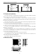
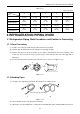
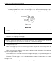
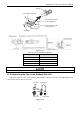
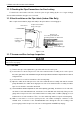
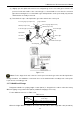
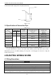
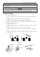
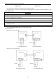
Table Of Contents
- 目录
- 第一部分 产品篇
- 第二部分 控制篇
- CONTROL
- 1 OPERATION FLOWCHART
- 2 WIRELESS REMOTE CONTROLLER
- 3 WIRED CONTROLLER
- 4 OPERATION INSTRUCTION OF SPECIAL FUNCTIONS
- 4.1 Setting of Filter Clean Reminder Function
- 4.2 Low Temperature Drying Function
- 4.3 Lock Function
- 4.4 Memory Function
- 4.5 Door Control Function/Human Sensitive Function
- 4.6 Switch between Fahrenheit and Centigrade
- 4.7 Enquiry of Ambient Temperature
- 4.8 Enquiry of Historical Malfunction
- 4.9 Debugging Function
- 4.9.1 Setting ambient temperature sensor (dual ambient temperature sensors function)
- 4.9.2 Selecting three speeds in high speed and three speeds in low speed of indoor fan motor
- 4.9.3 Displaying setting of freeze protection error code
- 4.9.4 Setting refrigerant lacking protection function
- 4.9.5 Selecting blowing residual heating of indoor unit
- 4.9.6 Mode selecting of compressor electric heating belt
- 4.9.7 Selecting low-power consumption mode
- 4.9.8 Selecting door control function
- 4.9.9 Selecting human sensitive function
- 4.9.10 Selecting long-distance monitoring or centralized controller
- 4.9.11 Selecting fan mode of indoor fan motor
- 4.9.12 Selecting compensation of temperature sensor at air return
- 5 INSTALLATION OF WIRED CONTROLLER
- 6 TROUBLESHOOTING
- 7 CENTRALIZED CONTROLLER
- 7.1 Smart Zone Controller
- 7.2 Additional Special Functions
- 7.2.1 Door control function
- 7.2.2 Human sensitive function
- 7.2.3 MODBUS interface
- 7.2.4 Connect to interface of centralized controller:
- 7.2.5 Light board control:
- 7.2.6 Malfunction output of relay:
- 7.2.7 Reserved fresh air valve interface for duct type unit
- 7.2.8 Interface of anion generator
- 7.2.9 Chassis electric heating belt of outdoor unit is optional
- CONTROL
- 第三部分 安装篇
- INSTALLATION
- 1 INDOOR UNIT INSTALLATION
- 1.1 Installation of Duct Type
- 1.2 Installation of Floor Ceiling Type
- 1.3 Installation of Cassette Type
- 1.3.1 Before Installation
- 1.3.2 Installation Site
- 1.3.3 Installing the Main Body Unit
- 1.3.4 Installing the Suspension Bolts
- 1.3.5 Leveling
- 1.3.6 The Panel Installation
- 1.3.7 Dimension Data
- 1.3.8 Installation of Drain Piping
- 1.3.9 Installing the Drain Pipes
- 1.3.10 Precautions When Doing Riser Piping Work
- 1.3.11 Testing of Drain Piping
- 2 OUTDOOR UNIT INSTALLATION
- 3 REFRIGERATION PIPING WORK
- 3.1 Refrigeration Piping Work Procedures and Caution in Connecting
- 3.2 Specification of Connection Pipe
- 4 ELECTRIC WIRING WORK
- 1 INDOOR UNIT INSTALLATION
- INSTALLATION
- 第四部分 维护篇(上)4.1~4.3
- 第四部分 维护篇(中)4.4拆装
- 第四部分 维护篇(下)4.5爆炸图及清单

U-Match Series DC Inverter Service Manual
85
an oil bend should be employed for every 6m (19-2/3 feet).
Oil bend
Indoor
Outdoor
6m(19-2/3feet)
Oil bend
Figure 3-3-8
3.2 Specification of Connection Pipe
Table 3-3-3
Item
Model
Size of Fitting Pipe
mm (inch)
Max. Pipe
Length
m (feet)
Max. Height Difference
between Indoor Unit and
Outdoor Unit
m (feet)
Drainage pipe(Outer
Diameter × wall
thickness)
mm (inch)
Liquid
Gas
GUHD18ND3FO
6(1/4)
12.7(1/2)
50(164)
15(49-1/5)
Φ17X1.75
(Φ5/8 X 7/100)
GUHD24ND3FO
9.5(3/8)
16(5/8)
50(164)
15(49-1/5)
Φ17X1.75
(Φ5/8 X 7/100)
GUHD30ND3FO
50(164)
15(49-1/5)
Φ17X1.75
(Φ5/8 X 7/100)
GUHD36ND3FO
50(164)
15(49-1/5)
Φ17X1.75
(Φ5/8 X 7/100)
GUHD42ND3FO
50(164)
15(49-1/5)
Φ17X1.75
(Φ5/8 X 7/100)
GUHD48ND3FO
70(229.7)
15(49-1/5)
Φ17X1.75
(Φ5/8 X 7/100)
The connection pipe should be insulated with proper water-proof insulating material.
The pipe wall thickness shall be 0.5~1.0mm (1/50~1/25inch) and the pipe wall shall be able to
withstand the pressure of 6.0MPa (870psig). The longer the connecting pipe, the lower the cooling and
heating effect performs.
4 ELECTRIC WIRING WORK
4.1 Wiring Precautions
①. Before obtaining access to terminals, all supply circuits must be disconnected.
②. The rated voltage of the unit is as shown as Table 1-4-1 and Table 1-4-2
③. Before turning on, verify that the voltage is within the 187~252V range (for single phrase units).
④. Always use a special branch circuit and install a special receptacle to supply power to the air conditioner.
⑤. Use a special branch circuit breaker and receptacle matched to the capacity of the air conditioner.
⑥. The special branch circuit breaker is installed in the permanent wiring. Always use a circuit that can trip all the poles
of the wiring and has an isolation distance of at least 3mm (1/8inch) between the contacts of each pole.