
Installation Manual
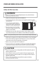

Indoor Unit
Display
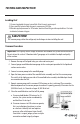
Outdoor Unit Indicators
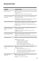
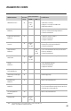
Malfunction Name Possible Causes
DIAGNOSTIC CODES
IPM Module Protection
Indoor DC Fan Motor
Malfunction
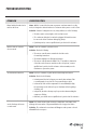
Compressor De-Synchronized
Malfunction
Power Factor Correction (PFC)
Protection
Outdoor Fan Motor
Malfunction
Incompatible Indoor and
Outdoor Units
Start-Up
Malfunction
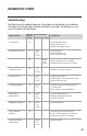
Compressor Phase-Current
Detection Malfunction
DC Bus Voltage Level Dropping
Malfunction
Current Detection
Malfunction
Reversing Valve
Malfunction
Zero Crossing Detection
Malfunction
Defrosting Status
1) IPM module over heating.
2) Improper or Low voltage at the IPM module.
3) IPM module malfunction.
1) Loose connections between fan motor and control board
2) Fan motor or blower wheel bearings malfunction.
3) Control board malfunction.
1) Compressor voltage is not balance.
2) Control board malfunction
3) Compressor malfunction
1) Mis-wiring of the reactor filter and PFC capacitor.
2) Reactor filter or PFC capacitor malfunction.
3) Control board malfunction.
1) Loose connections between fan motor and control board
2) Fan motor malfunction.
3) Control board malfunction.
Indoor and outdoor units are not compatible.
1) Over charged with refrigerant.
2) Control board malfunction.
3) Compressor malefaction.
Outdoor control board malfunction
Unstable supply voltage
Outdoor control board malfunction
1) Voltage to reversing valve is less than 175V.
2) Loose connections between reversing valve and control board.
3) Reversing valve solenoid malfunction.
Outdoor control board malfunction
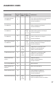
H5
H6
H7
HC
L3
LP
LC
U1
U2
U3
U4
U9
note 1
Yellow
4 flashes
and
1 sec Off
14 flashes
and
1 sec Off
16 flashes
and
1 sec Off
16 flashes
and
1 sec Off
Red
14 flashes
and
1 sec Off
Notes: 1) During defrosting process, the heating indicator is on for 10s and off for 0.5s.
2) Refer to Service Manual for additional information.
28