
Specification


2
Technical Data
September 2014
Dual Relay Switchpack
www.coopercontrol.com
Specifications
Electrical
Ratings
Input:
120/277 VAC, 50-60 Hz operation.
Contacts are isolated and may be used to control
low voltage circuits
Output:
24 VDC 125mA to operate up to five sensors
Control
Connecting the 22 AWG blue and yellow control
leads to the red lead will close the relay contacts
Ballast
Compatibility
Compatible with magnetic and electronic ballasts
NOTE
The life of some compact fluorescent lamps (CFLs)
is shortened by frequent automatic or manual
switching. Check with the CFL and ballast manu-
facturer to determine effects of cycling
Operating
Environment
Temperature: 32°F - 104°F (0°C - 40°C)
Relative humidity: Less than 95%, non-condensing
For indoor use only
Housing
Medium impact injection molded housing. ABS
resin complies with UL 94V-0. Plenum rated for
external junction box mounting, with Teflon coated
leads
Motor Load
1 HP 120 VAC; 2 HP 250 VAC
Size
4 3/4” x 2” x 3 1/4”
Mounting
Mounts directly to 4" square box
Standards
UL, CSA Listed
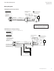
Description/Operation
The switchpack has three main components: a transformer and two
high current relays. The transformer has a primary line voltage input
and a secondary low voltage output. The low voltage output, 24
VDC, provides operating power to connected low voltage Greengate
occupancy sensors. When an occupancy sensor detects motion,
it electrically closes an internal circuit, pulling up the control signal
between the sensor and the switchpack. This signals the switchpack
to close its high current relays, turning connected loads on.
Applications
The switchpack is designed to work with low voltage Greengate
sensors which require switchpacks. It cannot be used with sensors
designed for use with any other low voltage relay systems. Consult
sensor spec sheets for other sensor/relay combinations.