® PN 452413 Canopy Type Kitchen Hoods Installation, Operation and Maintenance Manual Please read and save these instructions. Read carefully before attempting to assemble, install, operate or maintain the product described. Protect yourself and others by observing all safety information. Failure to comply with instructions could result in personal injury and/or property damage! Retain instructions for future reference.
Table of Contents Receiving and Handling . . . . . . . . . . . . . . . . . . . . . . . . . . . . . . . . . . . . . . . . . . . . . . . . . . . . . . . . . . . . . . 4 Storage . . . . . . . . . . . . . . . . . . . . . . . . . . . . . . . . . . . . . . . . . . . . . . . . . . . . . . . . . . . . . . . . . . . . . . . . . . . 4 Hood Weights . . . . . . . . . . . . . . . . . . . . . . . . . . . . . . . . . . . . . . . . . . . . . . . . . . . . . . . . . . . . . . . . . . . . . . 4 Installation . . . . . . . .
Table of Contents Maintenance . . . . . . . . . . . . . . . . . . . . . . . . . . . . . . . . . . . . . . . . . . . . . . . . . . . . . . . . . . . . . . . . . . . . . . 32 Grease Grabber™ Cleaning and Maintenance . . . . . . . . . . . . . . . . . . . . . . . . . . . . . . . . . . . . . . . 33 - 34 Filter Cleaning Frequency Chart . . . . . . . . . . . . . . . . . . . . . . . . . . . . . . . . . . . . . . . . . . . . . . . . . . . . . . 35 Troubleshooting Guide . . . . . . . . . . . . . . . . . . . . . . . .
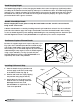
Receiving and Handling Upon receiving the equipment, check for both obvious and hidden damage. If damage is found, record all necessary information on the bill of lading and file a claim with the final carrier. Check to be sure that all parts of the shipment, including accessories, are accounted for. STORAGE If a kitchen hood must be stored prior to installation it must be protected from dirt and moisture. Indoor storage is recommended.
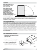
Installation NOTE: If you have a Back Supply Plenum (BSP), this must be installed before the hood. Please see Page 10. For Wall/Single Island Style Hoods, prior to installation, check with local authorities having jurisdiction on clearances to combustible surfaces, etc. Fig. 1 Bottom With the hood still inside its packing crate, position the unit beneath its installation location. Pallet Carefully remove the packing Protective Material crate.
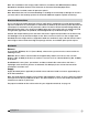
Hood Hanging Height The hood hanging height is critical, hanging the hood at the incorrect height may significantly reduce the ability for the hood to function properly and may be in violation of codes. The hood hanging height (typically, 78 in. (198.12 cm) above the finished floor) is given on the UL label located on the inside of the hood on the end panel. The hood must be hung level to operate properly. The grease trough is pitched to drain into the grease container.
Note: The installation of the canopy hoods shall be in accordance with NFPA 96 (latest edition), Standard for Ventilation Control & Fire Protection of Commercial Cooking Operations. After the hood is installed, remove all protective plastic. Note: Greenheck does not recommend walking or standing on the hood top as damage can result. If you must walk on the hood top, protect the hood with additional support or planks for flooring.
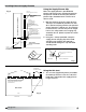
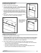
UMS Installing External Supply Plenums Using the Supply Plenum Clip HANGING METHODS FOR SUPPLY PLENUMS Fig. 6 Note: The supply plenum ASP, FSP AND VSP is provided with OPTION #1 = HANGING CLIP plenum clips that assist in hanging the plenum. OPTION #2 = UNI-STRUT The plenum should not be hung only with the OPTION #3 = THREADED ROD plenum clips, threaded rod or uni-strut must also be used.
YLE HOOD ATTACHED AIR CURTAIN CANOPY STYLE HOOD ATTACHED AIR CURTAIN CANOPY STYLE HOOD 1. Insert 1/2 in. (12.7 mm) diameter threaded rod (by others) into hanger brackets on the supply plenum top. Raise and hang the external supply plenum from adequate roof or ceiling supports. Fig. 9 ASP - Air Curtain Supply Plenum 2. The external supply plenum should be resting lightly against the hood. The hood is used to position the plenum only, it is not intended to support the plenum.
STEP 1 (IF MODULE < 6 ft.) Installing the Back Supply Plenum Installing the Supply Duct Collar 1. Find the center of the back supply plenum. L (MODULE LENGTH) 2. If the back supply plenum is less than 9 ft. 10 in. (299.72 cm) long, cut opening at the suggested location, centering the opening over the center of the back supply plenum. (Fig. 12) L/2 L/2 3. If the back supply plenum is greater than 9 ft. 10 in. (299.72 cm) long, divide the length of the back supply by four.
STEP 3 Hanging the Hood Before hanging the hood according to the hood installation instructions, please check the following: Fig. 15 1. Make sure the back supply plenum is properly secured, as described in steps 5 and 6, page 10. Hang 2. If the ductwork for the back supply will not interfere with the hood installation, it should be connected now. 3. Any filler panels should be attached to the hood before the hood installation. See page 5 for instructions.
Installing Enclosure Panels Before installing the enclosure panels, make sure the hood is hung in position with all the ductwork attached and electrical connections completed. Fig. 19 1. Position the end enclosure panels on the hood, and clamp into place with clamps provided or tackweld the panels into place (Fig 19). 2. Fasten the end enclosure panels to the wall, method depends on wall construction. (fasteners are not provided) If the hood is a double island, bolt the end enclosure panels together.
Installing End Skirts . Fig. 20 1. After the hood is hung in position, slide the hemmed form on top of the end skirt onto the end panels of the hood. 2. Drill a hole in the hood end panel to line up with the hole in the end skirt. Attach the end skirt with a 1/4 in. bolt and cap nut to the inside of the hood, or tack-weld the end skirt to the hood. 3. Position the end skirt against the wall and attach. The method depends on the wall construction. (fasteners for this are not provided) 4.
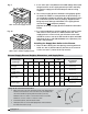
Installing Backsplash Panels FLAT BACKSPLASH PANEL MATERIAL GAUGE — STAINLESS Inches LENGTH Millimeters <= 48 <= 1219.2 1 WALL QTY >48<=94 >1219.2<=2387.6 2 >94<=141 >2387.6<=3581.4 3 >141<=188 >3581.4<=4775.2 4 >188<=235 >4775.2<=5969 5 HEIGHT LENGTH Fig. 21 NOTE: PANELS UP TO 48 IN. (1219.2 MM) WIDE SHIP IN ONE PIECE; OVER 48 IN. (1219.2 MM) IN MULTIPLE PIECES. INSULATED BACKSPLASH PANEL 1 IN. (25.4 MM) MATERIAL GAUGE — STAINLESS INSULATION — 1 IN. (25.
Installing Backsplash Panels HOOD END PANEL L HOOD FRONT PANEL SLIDE FLANGE BEHIND BACK OF THE HOOD BACKSPLASH PANEL SECTION VIEW OF BACKSPLASH PANEL OVERLAP HOLES SHOULD BE SPACED TO ADEQUATELY SECURE THE PANEL TO THE WALL STUDS (HOLE SPACING AND FASTENERS PROVIDED BY OTHERS) Fig. 23 1. After the hood is hung in position, slide the flat flange of the backsplash panel behind the back of the hood. Note: If the backsplash panel length is greater than 46 in. (116.
Installing Duct Collars 1. The exhaust duct connection needs to be located within 48 in. (121.92 cm) from the center of the hood length to the center of the duct connection. (see Fig. 24, back view Fig. 25) 2. The exhaust duct connection is to be a continuous liquidtight weld. Weld with a non-ferrous filler wire, such as silicon bronze or stainless steel filler wire. Protect all stainless steel areas from weld splatter. 3. The supply duct connection is tackwelded at 1 to 2 in. (2.54 to 5.
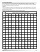
Exhaust Air Balancing Baffles (EABB) This is a guide to assist in determining if multiple hoods on one fan can be balanced to have equal static pressure. For multiple hoods on one fan to achieve their designed exhaust flow, all of the hoods must have equal static pressure at their designed exhaust flow. The laws of physics force the static pressure for each branch of a duct system on one fan to always be equal.
Balancing the Kitchen Exhaust System A. To determine the proper dining room air balance: 1. Refer to engineering drawings to determine total exhaust CFM from dining areas. (Exhaust fans, heating and air conditioning units, restrooms, etc.) 2. Determine the total CFM of make-up air supplied to dining area. 3. Subtract #1 from #2 above. If the result is a negative number, a negative pressure is present in the dining area. In this case, kitchen exhaust odors could be drawn from the kitchen to the dining area.
Measure the velocity of each location. A digital 2.75 in. (70 mm) rotating vane anemometer or equivalent is suggested. The center of the anemometer should be held 2 in. (50 mm) from the face of the filters as shown in Fig. 30. It is helpful to make a bracket to keep the anemometer at the 2 in. (50 mm) distance and parallel to the filter. Both squareness and distance are very important for accuracy. Airflow Rotating Vane Anemometer 2 in. Fig. 30 Calculate the average velocity for the filter. 3.
B. Supply (If Applicable): Example for Perforated Face Supply 1. Hood set up If the make-up air unit has a temperature control, it should be used to keep the supply air at the desired room discharge air temperature. 2. Measure Velocities Divide the perforated face panel into a grid of equal areas, each approximately 4 in. (100 mm) square. Measure the velocity at the center of each grid area. A digital 2.75 in. (70 mm) rotating vane anemometer or equivalent is suggested.
Testing Hood Air Volume Baffle Filters Style Hoods with the Shortridge Meter A. Exhaust With all the filters in place, determine the total hood exhaust volume with a Shortridge meter as follows: 1. All cooking equipment should be on. If the hood has internal short circuit make-up air, it should be turned off. 2. Measuring Velocities • Set up the Shortridge meter. • For 20 in. (500 mm) wide filters, position the grid as shown in Fig. 32 and 33. Average two measurements. • For 16 in.
High Velocity Cartridge Filters A. Exhaust 1/2 Width 1/4 Width 1/4 Width With all the filters in place, determine the total hood exhaust volume with a rotating vane anemometer as follows: 1/2 1. All cooking equipment should be on. If the hood has internal short circuit make-up air, it should be turned off. Inle 2. Measuring Velocities Fig. 35 • Velocity measurement should be taken at three locations per filter. These must be over the inlet opening as shown in Fig. 35. 2 in.
High Velocity Cartridge Filters A. Exhaust With all the filters in place, determine the total hood exhaust volume with a Shortridge meter as follows: 1. All cooking equipment should be on. If the hood has internal short circuit make-up air, it should be turned off. 2. Measuring Velocities • Set up the Shortridge meter. Leave all holes of Velgrid open. Do NOT tape over holes that are not over openings. The conversion factor takes this into account. • Position the grid over each filter as shown.
Grease-X-Tractor™ High Efficiency Filters or Grease Grabber™ Multi-Filtration System A. Exhaust With all the filters in place, determine the total hood exhaust 1/4 Width volume with a rotating vane anemometer as follows: 1. All cooking equipment should be off. If the hood has internal short circuit make-up air, it should be turned off. 1/2 Width 1/4 Width 1/2 Height Rotat Anem 2. Measuring Velocities • Measurement should be taken at six locations per filter.
Grease-X-Tractor™ High Efficiency Filters or Grease Grabber™ Multi-Filtration System A. Exhaust With all the filters in place, determine the total hood exhaust volume with a Shortridge meter as follows: 1. All cooking equipment should be on. If the hood has internal short circuit make-up air, it should be turned off. 2. Measuring Velocities • Set up the Shortridge meter. Leave all holes of Velgrid open. Do NOT tape over holes that are not over openings. The conversion factor takes this into account.
Testing Hood Air Volume Short Circuit Hoods Fig. 45 A. Supply All cooking equipment should be off. The hood exhaust should also be off. 1. Measuring Velocities • Velocity measurements should be made with a digital 2.75 in. (70 mm) rotating vane anemometer or its equivalent. • One velocity measurement should be taken for every 8 in. (200 mm) of short circuit opening length, starting tight against one edge of the opening, and finishing tight against the other edge.
Amerex Wiring Plan View POWER SOURCE MANUAL RESET RELAY PRM ELECTRIC GAS VALVE MICROSWITCH INSTALLER PROVIDED JUNCTION BOXES BASIC WIRING DIAGRAM POWER SOURCE MANUAL RESET RELAY RED (COMMON) YELLOW (N.O) BLACK (N.C.) GAS VALVE NOTE: DO NOT USE YELLOW WIRE ON MICROSWITCH IN NORMAL INSTALLATION. THE YELLOW WIRE IS TO BE USED ONLY FOR EXTINGUISHER ALARM, LIGHTS, CIRCUITS, ETC. MICROSWITCH BASIC WIRING DIAGRAM MANUAL RESET RELAY RED (COMMON) 120V/60HZ L1 L2 K1 Ka YELLOW (N.
Ansul Wiring Plan View Field Wiring for the Ansul Snap-Action Switch 2 Snap-Action Switches provided by Greenheck may be wired as shown. Four typical examples shown Option A Relay Part No. 14702 * K1a and K1b are N.O. when K1 is de-energized L1 Equipment Power to cooking equipment Black Red Shunt Trip Breaker NO 1 110V/60HZ L2 2 N.O. K1a NC Snap-Action Switch Part No. 423878 Input K1* 3 Brown 120 VAC N Manual Reset Relay Part No. 14702 5 6 K1b N.O.
Canopy Hood HOOD-1A FROM MAKE-UP AIR STARTER #2 TO CUBE FAN DISCONNECT SWITCH WIRED THROUGH BREATHER TUBE ONLY EXHAUST FAN-1A SUPPLY POWER TO JUNCTION BOX ON HOOD FOR HOOD LIGHTS FROM MAKE-UP AIR STARTER #3 TO CUBE FAN DISCONNECT SWITCH WIRED THROUGH BREATHER TUBE ONLY POWER PANEL SUPPLY POWER TO MAKE-UP AIR CONTROL CENTER BASIC WIRING DIAGRAM (WIRING BY OTHERS) HOOD-1B FIELD WIRING EXHAUST FAN-1B JUNCTION BOX ON TOP OF HOOD FOR FIELD CONNECTION OF SUPPLY POWER TWO (2) CONTROL WIRES FROM ANSU
Wiring for Hood Switch Panels THE DIAGRAMS BELOW SHOW A TYPICAL HOOD SWITCH PANEL REMOTE MOUNTED. The diagrams below show a typical hood switch panel remote mounted. For hood mounted switches FOR HOOD MOUNTED SWITCHES REFER TO THE WIRING CONNECTION DECAL ON THE refer to the wiring connection decal on the cover of the junction box on the hood top. COVER OF THE JUNCTION BOX ON THE HOOD TOP.
Circuit Diagrams Single Throw Single Pole Double Pole OFF OFF ON ON OFF OFF ON ON OFF OFF ON ON Double Throw ON (NC) ON (NC) ON (NC) ON (NO) ON (NO) ON (NO) ON (NC) ON (NO) ON (NC) ON (NO) ON (NC) ON (NO) Double Throw Center Off ON OFF ON OFF ON ON ON OFF ON Normally Closed Contacts Normally Open Contacts Series Circuit Off if both are not activated Off if either are not activated On if both are activated On if both are not activated Off if either are not activated Off if both
Maintenance Daily Maintenance 1. Wipe grease from exposed metal surfaces on the hood interior using a clean, dry cloth. 2. Visually inspect the filters or cartridges for grease accumulation. 3. Remove grease cup, empty contents, and replace cup. Weekly Maintenance 1. Remove the grease filters or cartridges and wash in dishwasher or pot sink. Note: Filters installed over heavy grease producing equipment may require more frequent cleaning. See filter cleaning schedule. 2.
Grease Grabber™ Filter Installation NOTE: Never install the Second Stage filter in the front filter channel. The Second Stage filter must be installed behind a UL Classified Grease-X-Tractor™ primary filter Model HE or GX. 1. Slide the top edge of the Second Stage filter into the top rear filter channel; Fig. 53. 2. Lifting the lower edge of the filter past the grease trough, continue to push the top of the filter into the channel. 3.
Grease Grabber™ Filter Cleaning Step 1 Remove the front GX filters: (1A) Remove middle filters first, (1B) slide ends toward middle and remove. GX Filters, first row of filters Step 2 1A 1B GG Filters, second row of filters 1C Release the hooks that hold the filters together. Slide the top hook upward and the bottom hook downward until the hook releases. Do this to all filters.
Filter Washing Frequency Guide Note: Standard cooking will turn the beads yellow in color. Open flame cooking will cause the beads to blacken. Neither affects the performance of the beads. Caution: To prevent damage to filter media, do not wash second stage filters in detergents that contain hydroxides such as sodium hydroxide or potassium hydroxide.
Troubleshooting Problem: Exhaust fan is not operating or is not operating at design levels. Is the fan receiving power? Replace fuses, reset circuit breakers, check disconnect. Is the belt loose or broken? Replace or tighten belt. Is the fan rotating in correct direction? Have the electrician correctly wire the fan. Is the make-up air operating? Problems with make-up air may interfere with the exhaust fan check the manufacturers installation manual.
Troubleshooting Problem: Smoke blows away before reaching the bottom of the hood. Are there pass-thru windows near the hood? Adjust amount and locations of make-up air to eliminate drafts through the pass-thru windows. Is this an air curtain hood? Turn off or reduce the amount of make-up air. Is the make-up air part of the hood or an attached plenum? Try turning off or reducing the amount of make-up air; block off portions of the supply to direct air away from the problem area (test with cardboard).
Before calling your manufacturers representative to report a problem have the following information available: 1. 2. 3. 4. 5. 6. 7. 8. 9. 10. 11. 12. Review / summary of troubleshooting section in installation operation manual. Hood model and serial number. Current cooking equipment line-up. Size of hood (length, width and height). Island or wall configuration. Multiple hoods on one fan. Nature of spillage (one end; all around the edges).
Replacement Parts GREENHECK PART NUMBER 452700 24 x 8 Aluminum Single Deflection H-OB 452701 36 x 8 Aluminum Single Deflection H-OB 452702 36 x 8 Aluminum Single Deflection H-OB 452703 44 x 8 Aluminum Single Deflection H-OB 453796 24 x 12 Aluminum Single Deflection H-OB 453797 36 x 12 Aluminum Single Deflection H-OB 453798 38 x 12 Aluminum Single Deflection H-OB 453799 44 x 12 Aluminum Single Deflection H-OB 452729 24 x 8 Aluminum 38° Fixed Blade RA-OB 452730 30 x 8 Aluminum 38° Fixed Bl
Warranty Greenheck warrants this equipment to be free from defects in material and workmanship for a period of one year from the shipment date. Any units or parts which prove defective during the warranty period will be replaced at our option when returned to our factory, transportation prepaid. Motors are warranted by the motor manufacturer for a period of one year.