
- Greenheck Combination Fire Smoke Dampers Installation Instructions

Refer to:
‘Installation Instructions for FSD-XXX, DFD-XXX, CFSD-XXX, &
SSFSD-XXX, Series Fire & Combination Fire Smoke Dampers’
(Part #461336)
INSTALLATION INSTRUCTION SUPPLEMENT
Part Number 463543
FSD Series
Field Supplied Sleeves on Fire
Smoke Dampers
“UL CLASSIFIED
(see complete marking on product)”
“UL CLASSIFIED to Canadian safety standards
(see complete marking on product)”
Standards UL 555 & UL 555S
Classifications Filed at UL under Listing #R13317
1. GAUGES AND LENGTHS OF FIRE DAMPER
SLEEVES
All fire smoke dampers must be installed in a steel sleeve
of the required gauge and length. See Table 1 for required
minimum sleeve gauges. Maximum sleeve thickness is
10 gauge (3.5mm). Sleeve inside dimensions must equal
damper outside dimensions.
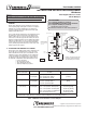
Sleeves shall extend a maximum of 16 in. (406mm) beyond
the wall or floor on the actuator side of the damper (see
Figure 1). When an access door is incorporated as a part
of the sleeve on the side opposite the actuator, the sleeve
shall also extend a maximum of 16 in. (406mm) beyond the
wall or floor. When there is no access door incorporated
as part of the sleeve, the sleeve shall extend a maximum
of 6 in. (152mm) beyond the wall or floor on the side of the
damper opposite the actuator.
2. ATTACHING FIRE DAMPERS TO SLEEVES
All four sides of the damper frame must be attached to the
sleeve with one row of attachments on each side of the
frame. Attachments must be spaced a maximum of 6 in.
(152mm) on centers and a maximum of 2 in. (51mm) from
corners. A minimum of 4 attachments (2 on each side of
the frame) per side (16 per damper) are required. One of
the methods of attachment shown below must be used.
• tack or spot welds
• #10 sheet metal screws
•
1
/4 in. (6mm)bolts and nuts
•
3
/16 in. (4.7mm)steel pop rivets
Dampers may be mounted either
vertically or horizontally. Blade
axis must always be horizontal.
Fig. 1
0QUJPOBMCMBEFJOEJDBUPS
BOEPSFMFDUSJDMJOL
,).%/&7!,,
$/./4).34!,,3#2%73
"%47%%.4(%3%,).%3
!2/5.$%.4)2%$!-0%2
$MFBSBODFGPSFYQBOTJPO
JONJOJONBY
3FUBJOJOH"OHMFT
TFF4FDUJPO
-*OFPG8BMM
"JSnPX
%FUBJM
%0/05*/45"--4$3&84
#&58&&/5)&4&-*/&4
"306/%&/5*3&%".1&3
"DDFTTEPPSSFRVJSFEPO
KBDLTIBGUTJEFPGEBNQFS
3FGFSUPUIFMBUFTUFEJUJPO
PG/'1""
+BDLTIBGU
"DUVBUPS
%BNQFS
4MFFWF
4MFFWF-FOHUI-
JONBY
JONBY
A"%JN
%JTUBODFGSPN
FOEPGTMFFWFUP
GBDFPGEBNQFS
5
X
$
-
Table 1: Minimum sleeve thickness for fire dampers.
Minimum Sleeve Thickness for Fire Dampers
Type of Duct to
Sleeve Connection
Duct Duct Dimension
in. (mm)
Sleeve Gauge
Rigid Round
Rectangular
24 in. (610mm) max. diameter
36 in. (914mm) max. width or
24 in. (610mm) max. height
16 (.060 in.)
[1.5mm]
Rigid Round
Rectangular
over 24 in. (610mm) diameter
over 36 in. (914mm) width or
over 24 in. (610mm) height
14 (.075 in.)
[2mm]
Breakaway
(or no duct)
Round or
Rectangular
12 in. (305mm) wide and under
13 in. - 30 in. (330mm - 762mm) wide
31 in. - 54 in. (787mm - 1371mm) wide
55 in. - 84 in. (1397mm - 2134mm) wide
85 in. (2159mm) wide and over
26 (.018 in.) [.46mm]
24 (.024 in.) [.6mm]
22 (.030 in.) [.76mm]
20 (.036 in.) [.9mm]
18 (.048 in.) [1.2mm]
Important Note: Sleeve thickness must not be less than the gauge of the connecting duct.
UL Standard 555 requires all ducts to terminate at the fire damper sleeves or the damper frames.
Copyright © 2008 Greenheck Fan Corporation
463543 Field Installed Sleeve Supplement Rev. 2 March 2008