
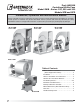
Corp. Fan User Manual


3
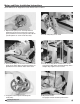
Installation
Inspect the unit for any damage and report it to
the shipper immediately. Also, check to see that all
accessory items are accounted for.
Move the fan to the desired location and fasten
securely through mounting holes provided in the base
angles. The unit must be set level (shimming may be
necessary). Flexible duct connections and vibration
isolators should be used where noise is a factor.
The motor voltage and ampere rating must be
checked for compatibility with the electrical supply
prior to final electrical connection. Supply wiring to the
fan must be properly fused, and conform to local and
national electrical codes.
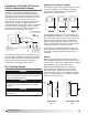
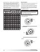
The discharge is factory set as specified by customer
order, however, it can be rotated to other discharge
positions in the field if necessary. Removal of the
housing bolts allows the discharge to be rotated to
the clockwise positions below. For TAD, BD and BAD
discharge positions, a portion of the frame angle must
be removed.
Clockwise rotation shown. Counterclockwise
discharge positions are a mirror image of those
shown. Fan rotation is always specified from the
drive side of the housing.
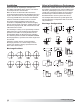
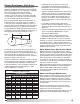
Affect of Installation on Performance
Restricted or unstable flow at the fan inlet can cause
pre-rotation of incoming air or uneven loading of the
fan wheel, yielding large system losses, increased
sound levels and structural failure of the fan wheel.
Free discharge or turbulent flow in the discharge
ductwork will also result in system effect losses.
The examples below show the system layout and
inlet and discharge configurations which can affect
fan performance.
GOOD
POOR
POOR
FAIR
7
o
MAX.
POOR
FAIR
POOR
FAIR
One
Impeller
Dia.
GOOD
Should be at least
1/2 Impeller Dia.
FAIR
Not Greater than
60
o
Including Angle
POOR
POOR
FAIR
GOOD
POOR
Turning
Varies
CW BH CW BAU CW TAUCW UB
CW TH CW TAD
CW BAD
CW DB
Discharge Positions
Discharge Configurations
3
Centrifugal Utility Fans
®