
Manual


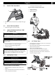
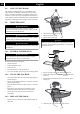
Table Of Contents
- 1 Description
- 2 Important safety instructions
- 3 Symbols on the machine
- 4 Risk levels
- 5 Service
- 6 Environmentally safe battery disposal
- 7 Proposition 65
- 8 Installation
- 9 Operation
- 10 Maintenance
- 11 Transportation and storage
- 12 Troubleshooting
- 13 Technical data
- 14 Limited warranty
- 15 Exploded view
- 1 Description
- 2 Instructions importantes sur la sécurité
- 3 Symboles figurant sur la machine
- 4 Niveaux de risques
- 5 Service
- 6 Élimination des batteries sans danger pour l'environnement
- 7 Proposition 65
- 8 Installation
- 9 Utilisation
- 10 Entretien
- 11 Transport et entreposage
- 12 Dépannage
- 13 Données techniques
- 14 Garantie limitée
- 15 Vue éclatées
- 1 Descripción
- 2 Instrucciones importantes de seguridad
- 3 Símbolos en la máquina
- 4 Niveles de riesgo
- 5 Servicio
- 6 Eliminación de batería segura para el medio ambiente
- 7 Propuesta 65
- 8 Instalación
- 9 Funcionamiento
- 10 Mantenimiento
- 11 Transporte y almacenamiento
- 12 Solución de problemas
- 13 Datos técnicos
- 14 Garantía limitada
- 15 Vista despiezada

WARNING
• If the parts are damaged, do not use the machine.
• If you do not have all the parts, do not operate the
machine.
• If the parts are damaged or missing, speak to the service
center.
1. Open the package.
2. Read the documentation in the box.
3. Remove all the unassembled parts from the box.
4. Remove the machine from the box.
5. Discard the box and package in compliance with local
regulations.
8.2 ATTACH THE EDGE GUIDE
NOTE
The edge guide can limit the cutting range of the machine
and decrease the risk of the damage caused by the rotating
cutting line.
1. Push the edge guide onto the trimmer head until it
engages in the slots.
2. The edge guide can be flipped up for storage.
8.3 ATTACH THE GUARD
1. Remove the screws from the trimmer head with a Phillips
head screwdriver (not included).
2. Put the guard onto the trimmer head.
3. Align the screw holes on the guard with the screw holes
on the trimmer head.
4. Tighten the screws.
8.4 ASSEMBLE THE SHAFT
WARNING
Never install, remove, or adjust any part of a machine while
the machine is plugged in or running.
NOTE
When you remove the machine from the box, the three
poles of the machine are connected by an electrical cord as
shown.
1. Push in the release button located on the middle shaft (4).
1
2
2. Align the release button (2) with the positioning hole (1)
on the upper shaft (3) and slide the two shafts together
until the button locks into the positioning hole.
7
English
EN