ST60L04 ST60L254 EN STRING TRIMMER OPERATOR MANUAL ES CORTABORDES MANUAL DEL OPERADOR STC404 www.greenworkstools.
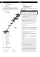
English 1 1.1 1.2 1.3 2 3 4 5 6 7 8 8.1 8.2 8.3 8.4 8.5 8.6 9 9.1 9.2 9.3 9.4 9.5 9.6 9.7 9.8 Description......................................... 4 Purpose.............................................................. 4 Overview........................................................... 4 Packing list........................................................ 4 Important safety instructions...........4 Symbols on the machine................... 5 Risk levels...........................................
English EN 1 DESCRIPTION 1.1 PURPOSE 6 Shoulder strap 2 This machine is used to cut grass, light weeds, and other similar vegetation at or around ground level. The cutting plane must be approximately parallel to the ground surface. You cannot use the machine to cut or chop hedges, shrubs, bushes, flowers and compost. 1.2 READ ALL INSTRUCTIONS BEFORE USING (THIS POWER TOOL) WARNING Read and understand all instructions before using this product.
English • • • • • • • • • • • • clean, and free from oil and grease. Failure to do so can cause serious injury. Check damaged parts before using the appliance, a guard or other part that is damaged should be carefully checked to determine that it will operate properly and perform its intended function. Check for alignment of moving parts, binding of moving parts, breakage of parts, damaged mountings, and any other condition that may affect its operation.
English EN 4 RISK LEVELS WARNING If the battery pack cracks or breaks, with or without leaks, do not recharge it and do not use. Discard it and replace with a new battery pack. DO NOT TRY TO REPAIR IT! To prevent injury and risk of fire, explosion, or electric shock, and to avoid damage to the environment: The following signal words and meanings are intended to explain the levels of risk associated with this product.
English EN WARNING • • • 8 If parts of the machine are damaged, do not use the machine. If you do not have all the parts, do not operate the machine. If the parts are damaged or missing, contact the service center. Release button 6 Positioning hole 1. Open the package. 4. Turn the lower shaft until the button locks into the positioning hole. 2. Read the documentation in the box. 3. Remove all the unassembled parts from the box. 5. Tighten the screw with the hex wrench (13). 4.
English EN 8.5 INSTALL THE BATTERY PACK WARNING Be careful when you operate the machine. WARNING • • • If the battery pack or charger is damaged, replace the battery pack or the charger. Stop the machine and wait until the motor stops before you install or remove the battery pack. Read and understand the instructions in the battery and charger manual. 9.1 START THE MACHINE 1. Push the lock-out button (3) and pull the trigger (4). 1.
English 9.4 ADJUST THE CUTTING DIAMETER EN 1. Attach the carabiner to the carrying ring on the drive tube. NOTE ① The machine is set at a 14 in. (35.6 cm) cutting diameter. You can adjust to a 16 in. (40.6 cm) cutting diameter. Set the cutting diameter to 14 in. (35.6 cm) for greater runtime and 16 in. (40.6 cm)for a larger cutting area. 1. Remove the battery pack. 2. Remove the blade screws from the cut-off blade (17). 3. Turn the cut-off blade 180°. 4. Tighten the blade screws. ② 17 2.
English EN IMPORTANT Make sure that all nuts, bolts and screws are tight. Examine regularly that you install the handles tightly. IMPORTANT Use only the replacement parts and accessories of the initial manufacturer. 10.1 GENERAL INFORMATION IMPORTANT Only your dealer or approved service center can perform maintenance that is not given in this manual. Before the maintenance operations: 9.8 • • • • • • CUTTING TIPS Tilt the machine toward the area to be cut.
English b a c e EN d a b 3. Insert the line into the mounting hole, which is located inside the eyelet (b). Push the cutting line until it exits the opposite hole. 3. Remove any remaining line. 4. Clean dirt and debris from all parts. Replace spool (d) if it is worn or damaged. 5. Align the spool tabs (a) with the tab openings in the base of the spool (e). Mounting Hole inside the Eyelet 4. Pull the cutting line through until there is an equal quantity of cutting line on each side. 6.
English EN 10.5 REPLACE THE SPOOL NOTE If any parts of the spool retainer assembly are damaged or worn, replace the damaged part and reassemble them as following showing b 1. Disassemble the trimmer head . Pull and remove the spool cover (b). b a c a d 2. Turn the trimmer head clockwise to loosen it. Do not remove the spacer from the shaft. 2. Clean dirt and debris from all parts. Replace spool (d) if it is worn or damaged. 3. Loosen the screws (e).
English 11 TRANSPORTATION AND STORAGE WARNING Remove the battery pack from the machine before transportation and storage. 11.1 Stop the machine. Remove the battery pack. 11.2 • • • • STORE THE MACHINE Remove the battery pack from the machine. Make sure that children cannot come near the machine. Keep the machine away from corrosive agents such as garden chemicals and de-icing salts. Secure the machine during transportion to prevent damage or injury. Clean and examine the machine for any damage.
English EN 13 TROUBLESHOOTING Problem Possible Cause Solution The machine does not start No electrical contact between the mawhen you push the trigger. chine and the battery pack. The machine stops when you cut. 1. Remove battery pack. 2. Check contact and install the battery pack again. The battery pack is depleted. Charge the battery pack. The lock-out button and trigger are not pushed at the same time. 1. Push the lock-out button and hold it. 2. Pull the trigger to start the machine.
English EN Problem Possible Cause Solution Vibration increases obviously. The line is worn down at one side and not advanced in time. Make sure that the line on both sides is normal. Advance the line. 14 LIMITED WARRANTY Mooresville, NC 28115 Greenworks hereby warranties this product, to the original purchaser with proof of purchase, for a period of four (4) years against defects in materials, parts or workmanship.
English EN 15 EXPLODED VIEW 1.1 1 1.2 2 1.3 1.4 6 3 5 4 No. Part No. Qt y Description No. Part No. Qty Description 1 R0201836-00 1 Auxiliary Handle Assembly 2 R0201834-00 1 Trimmer Head Assembly 1.1 R0201826-00 1 Bolt 3 R0201830-00 1 Hex Screw 1.2 R0201827-00 1 Auxiliary handle 4 R0201881-00 1 Guard Assembly 1.3 R0201828-00 1 Bracket 5 R0201770-00 1 Allen key 1.
Español 1 1.1 1.2 1.3 2 3 4 5 6 7 8 8.1 8.2 8.3 8.4 8.5 8.6 9 9.1 9.2 Descripción.......................................18 Finalidad.......................................................... 18 Perspectiva general.......................................... 18 Lista de embalaje............................................. 18 Instrucciones importantes de seguridad.......................................... 18 Símbolos en la máquina.................. 19 Niveles de riesgo..............................
Español ES 1 DESCRIPCIÓN 1.1 FINALIDAD 6 Correa de hombro 2 Esta máquina se utiliza para cortar hierba, maleza ligera y otra vegetación similar a nivel del suelo. El plano de corte debe estar aproximadamente paralelo a la superficie del suelo. No puede utilizar la máquina para cortar o podar setos, arbustos, matorrales, flores y compost. 1.
Español • • • • • • • • manera. Asegúrese de que el cabezal de hilo esté correctamente instalado y bien fijado. Mantenga el filo afilado y limpio para un mejor rendimiento y para reducir el riesgo de lesiones. Siga las instrucciones para la lubricación y el cambio de accesorios. Inspeccione periódicamente el cable del aparato, y si está dañado, haga que lo repare un centro de servicio técnico autorizado. Inspeccione periódicamente los cables alargadores y sustitúyalos si están dañados.
Español Símbolo ES Utilice únicamente accesorios y piezas de repuesto idénticos del fabricante. Explicación Debe leer y entender todas las instrucciones antes de manejar la máquina, así como seguir todas las advertencias e instrucciones de seguridad. 6 Lleve siempre gafas de seguridad con protectores laterales marcada para cumplir la ANSI Z87.1 cuando utilice esta máquina. ELIMINACIÓN DE BATERÍA SEGURA PARA EL MEDIO AMBIENTE No exponga la máquina a la lluvia o a condiciones de humedad.
Español 7 PROPUESTA 65 3. Alinee los orificios de tornillos de la protección con los orificios de tornillo del cabezal de corte. AVISO 4. Apriete los tornillos. Este producto contiene una sustancia química conocida en el estado de California como causante de cáncer, defectos de nacimiento u otros daños reproductivos.
Español ES 8.4 FIJACIÓN DEL ASA AUXILIAR Presionar para soltar 1. Retire el mando (16) del asa. 2. Fije el asa auxiliar y la abrazadera inferior (15) en el eje. 3. Sitúe el asa auxiliar en una posición cómoda. 4. Introduzca el perno (14) por el orificio. 5. Apriete el asa auxiliar con el mando. 14 7 9 15 FUNCIONAMIENTO IMPORTANTE 16 Antes de utilizar la máquina, debe leer y entender las normas de seguridad y las instrucciones de funcionamiento. 8.
Español eficiencia del corte disminuya. Esto mantendrá el mejor rendimiento y mantendrá el hilo el tiempo suficiente para avanzar adecuadamente. 2. El hilo se libera automáticamente y la cuchilla de corte corta la longitud sobrante. 9.6 ES FIJACIÓN DE LA MÁQUINA A LA CORREA DE HOMBRO ② ① ① ② 9.4 AJUSTE DEL DIÁMETRO DE CORTE NOTA 1. Fije el mosquetón al anillo de transporte en el tubo de accionamiento. La máquina está ajustada a un diámetro de corte de 14 in. (35.6 cm).
Español 10 Le sugerimos lo siguiente cuando utilice la máquina ES • • Mantenga una posición firme con las dos manos en la máquina mientras cabezal de hilo está girando. Corte la hierba alta de arriba a abajo. IMPORTANTE Debe leer y entender los reglamentos de seguridad y las instrucciones de mantenimiento antes de limpiar, reparar o realizar tareas de mantenimiento en la máquina. Si se enrolla hierba alrededor del cabezal de corte: • • MANTENIMIENTO Retire la batería. Quite la hierba.
Español ES a 10.4 2. Tire para retirar la cubierta del carrete (b). b a c e INSTALACIÓN DEL HILO DE CORTE NOTA No ponga más de 15 ft (5 m) de hilo de corte cada vez. d 1. Retire el hilo de corte restante del carrete. 2. Alinee las ranuras de la cubierta del carrete con las ranuras (a) del cabezal de corte. 3. Retire el hilo restante. 4. Limpie la suciedad y los residuos de todas las piezas. Sustituya el carrete (d) si está desgastado o dañado. a 5.
Español 3. Afloje los tornillos (e). Retire el carrete (d), la cubierta de la ranura (f) y la carcasa de ubicación (g) del conjunto del carrete. ES 4. Sustituya por un carrete nuevo. 5. Inserte la carcasa de ubicación y la cubierta de la ranura en la cubierta del carrete (b), a continuación, coloque el carrete sobre la cubierta de la ranura en la posición deseada. 6. Apriete con los tornillos. 5.
Español 11.2 • • • • 10.7 Retire la batería de la máquina. Asegúrese de que los niños no puedan acercarse a la máquina. Mantenga la máquina alejada de agentes corrosivos, como sustancias químicas para jardín y sales para descongelación. Fije la máquina durante el transporte para evitar daños o lesiones. Limpie y examine si hay daños en la máquina. 12 MONTAJE DEL CABEZAL DE CORTE ALMACENAMIENTO DE LA MÁQUINA DATOS TÉCNICOS Tipo 1.
Español ES 13 SOLUCIÓN DE PROBLEMAS Problema Posible causa La máquina no se pone en marcha cuando aprieta el gatillo. No hay contacto eléctrico entre la máqui- 1. Retire la batería. na y la batería. 2. Compruebe el contacto e instale de nuevo la batería. La máquina se detiene cuando corta. Solución La batería se ha agotado. Cargue la batería. El botón de desbloqueo y el gatillo no se presionan al mismo tiempo. 1. Pulse el botón de desbloqueo y manténgalo pulsado.
Español Problema Posible causa Solución La hierba se enrolla alrededor del cabezal de corte y de la carcasa del motor. Corte la hierba alta al nivel del suelo. 1. Corte la hierba alta de arriba a abajo. El hilo no corta bien. La cuchilla de corte se ha desafilado. Las vibraciones aumentan notablemente. El hilo está gastado en un lado y no se ha Asegúrese de que el hilo a ambos lados esté normal. avanzado a tiempo. Avance el hilo. 14 2.
Español ES 15 VISTA DESPIEZADA 1.1 1 1.2 2 1.3 1.4 6 3 5 4 Nº Nº pieza Ca Descripción nt. Nº Nº pieza Ca nt.