5" 5.5A ELECTRIC STRING TRIMMER 21272 Owner’s Manual TOLL-FREE HELPLINE: 1-888-90WORKS (888.909.6757) Read all safety rules and instructions carefully before operating this tool.
CONTENTS Contents .............................................................................................................................. 2 ...................................................................................................................... 2 Important Safety Instructions ............................................................................................3 - 5 Symbols ............................................................................................................
IMPORTANT SAFETY INSTRUCTIONS WA R N I N G Read and understand all instructions. Failure to follow all instructions listed below may result in electric shock, fire and/or serious personal injury. • For safe operation, read and understand all instructions before using this product. Follow all safety instructions. Failure to follow all safety instructions listed below, can result in serious personal injury. • Do not allow children or untrained individuals to use this unit.
IMPORTANT SAFETY INSTRUCTIONS WA R N I N G To reduce the risk of electric shock - Use outdoor extension cords marked W-A, W, SW-A, SOW-A, STW-A, STOW-A, SJW-A, SJTW-A, or SJTOW-A. These cords are rated for outdoor use and reduce the risk of electric shock. • Use Right Appliance - Do not force tool. Use the correct tool for your application. The correct tool will do the job better and safer at the rate for which it is designed.
IMPORTANT SAFETY INSTRUCTIONS • Make sure your extension cord is in good condition. When using an extension cord, be sure to use one heavy enough to carry the current your product will draw. A wire gauge size (A.W.G.) of at least 16 is recommended for an extension cord 50 feet or less in length. A cord exceeding 100 feet is not recommended. If in doubt, use the next heavier gauge. The smaller the gauge number, the heavier the cord.
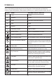
SymbolS Some of the following symbols may be used on this product. Please study them and learn their meaning. Proper inter-pretation of these symbols will allow you to operate the product better and safer.
SYMBOLS The following signal words and meanings are intended to explain the levels of risk associated with this product. SYMBOL SIGNAL MEANING DANGER Indicates an imminently hazardous situation, which, if not avoided, will result in death or serious injury. WARNING Indicates a potentially hazardous situation, which, if not avoided, could result in death or serious injury. CAUTION Indicates a potentially hazardous situation, which, if not avoided, may result in minor or moderate injury.
ELECTRICAL DOUBLE INSULATED Double insulation is a concept in safety in electric power tools, which eliminates the need for the usual threewire grounded power cord. All exposed metal parts are isolated from the internal metal motor components with protecting insulation. Double insulated tools do not need to be grounded.. WA R N I N G The double insulated system is intended to protect the user from shock resulting from a break in the tool’s internal insulation.
ELECTRICAL **Ampere rating (on tool faceplate) MINIMUM GAUGE FOR EXTENSION CORDS (AWG) (WHEN USING 120V ONLY) Amp Rating Total Length of Cord in Feet (meters) More Than Not More Than 25' (7.6 m) 50' (15 m) 0 6 10 12 6 10 12 16 18 18 16 14 16 16 16 12 100' (30.4 m) 150' (45.7 m) 16 14 14 12 14 12 Not Recommended When working with the tool outdoors, use an extension cord that is designed for outside use. This is indicated by the letters “WA” on the cord’s jacket.
FEATURES ADJUSTABLE FRONT HANDLE TRIMMER / EDGER SHIFT BUTTON FLOWER GUARD REAR HANDLE CORD RETAINER TELESCOPING BOOM COUPLER GRASS DEFLECTOR Fig. 1 KNOW YOUR STRING TIMMER (See Fig. 1) The safe use of this product requires an understanding of the information on the tool and in this operator’s manual as well as a knowledge of the project you are attempting. Before use of this product, familiarize yourself with all operating features and safety rules.
ASSEMBLY UNPACKING • This product requires assembly. • Carefully remove the product and any accessories from the box. Make sure that all items listed in the packing list are included. • Inspect the product carefully to make sure no breakage or damage occurred during shipping. • Do not discard the packing material until you have carefully inspected and satisfactorily operated the product. • If any parts are damaged or missing, please call 1-888- 909-6757 for assistance.
ASSEMBLY FRONT HANDLE Fig. 2 GUARD Fig. 3 PHILLIPS HEAD SCREW GUIDE HOLE GUIDE GROOVE 12 Fig.
ASSEMBLY ATTACHING SHAFT (See Fig. 4 ) • Unlock the cam lever and insert the lower shaft through the guide groove till hearing "click". • Unlock the cam lever and stretch the shaft to the suitable position, then lock the knob STARTING/STOPPING THE TRIMMER (See Fig. 5 ) Attach the outlet end of an extension cord to the plug on the rear of the string trimmer. NOTE: Use only approved outdoor extension cords.
assembly • Trimmer should be held at a comfortable position with the rear handle about hip height. • Cut tall grass from the top down. This will prevent grass from wrapping around the shaft housing and string head IF GRASS BECOMES WRAPPED AROUND THE STRING HEAD: • Stop the trimmer. • Unplug the string trimmer. • Remove the grass. operation WA R N I N G Always hold the string trimmer away from the body keeping clearance between the body and the string trimmer.
OPERATION CUTTING TIPS (See Fig. 7) • Keep the trimmer tilted toward the area being cut; this is the best cutting area. • The string trimmer cuts when passing the unit from left to right. This will avoid throwing debris at the operator. • Use the tip of the string to do the cutting; do not force string head into uncut grass. • Wire and picket fences cause extra string wear, even breakage. Stone and brick walls, curbs, and wood may wear strings rapidly. • Avoid trees and shrubs.
OPERATION ADJUST(2) PRESS(1) TELESCOPING BOOM COUPLER Fig. 8 Fig. 9 EDGING (See Fig. 10) Unplug the trimmer. Press the shift button and rotate the trimmer head 90° then fix the trimmer head. 90° PRESS(1) Fig.
MAINTENANCE WA R N I N G When servicing, use only identical replacement parts. Use of any other parts may create a hazard or cause product damage. WA R N I N G Always wear safety goggles or safety glasses with side shields that comply with ANSI Z87.1 during power tool operation or when blowing dust. If operation is dusty, also wear a dust mask. WA R N I N G Before inspecting, cleaning or servicing the unit, stop the motor, wait for all moving parts to stop, and disconnect from power supply.
MAINTENANCE • Install the new spool so that the strings and slots align with the eyelets in the string head. Thread the strings into the eyelets. • Pull the strings extending from the string head so the string releases from the slots in the spool. • Reinstall the spool retainer by depressing tabs into slots and pushing down until spool retainer clicks into place. WIND CLOCKWISE SPOOL RETAINER SPOOL TABS SPOOL SPOOL SLOTS HOLE Fig. 11 Fig. 12 STRING REPLACEMENT (See Fig. 11 - 12.
MAINTENANCE STORING THE TRIMMER • Open telescoping boom coupler and set at shortest setting. • Clean all foreign material from the trimmer. • Store it in a place that is inaccessible to children. • Keep away from corrosive agents such as garden chemicals and de-icing salts. TROUBLESHOOTING PROBLEM POSSIBLE CAUSE SOLUTION Strings will not advance when using the Auto Feed Head: 1. Strings are welded to themselves. 2. Not enough string on spool. 3. Strings are worn too short. 4.
WARRANTY GREENWORKS™ hereby warranties this product, to the original purchaser with proof of purchase, for a period of four (4) years against defects in materials, parts or workmanship. GREENWORKS™, at its own discretion will repair or replace any and all parts found to be defective, through normal use, free of charge to the customer.
PARTS 21
PARTS LIST ITEM NO. 1 2 3 4 5 6 7 8 9 10 11 12 13 14 15 16 17 18 19 20 21 22 23 24 25 26 27 28 29 30 31 32 33 34 35 36 37 38 39 40 41 42 PART NO.
PARTS LIST ITEM NO. 43 44 45 46 47 48 49 50 51 52 53 54 55 PART NO.
TOLL-FREE HELPLINE: 1-888-90WORKS (888.909.