80V 16” Cordless String Trimmer ST80L00 Owner’s Manual TOLL-FREE HELPLINE: 1-855-345-3934 www.greenworkstools.com/80v-pro Read all safety rules and instructions carefully before operating this tool.
CONTENTS Contents............................................................................................................................... 2 Product Specifications ......................................................................................................... 2 Important Safety Instructions................................................................................................ 3 Symbols...................................................................................................
important safety instructions WA R N I N G Read and understand all instructions before using this product. Failure to follow all instructions listed below may result in electric shock, fire, and/or serious personal injury. • Use only identical manufacturer’s replacement parts and accessories. Use of any other parts may create a hazard or cause product damage. • Always wear safety glasses with side shields marked to comply with ANSI Z87.1. Everyday glasses have only impact resistant lenses.
important safety instructions • Do not dispose of the batteries in a fire. The cells may explode. Check with local codes for possible special disposal instructions. • Do not open or mutilate the batteries. Released electrolyte is corrosive and may cause damage to the eyes or skin. It may be toxic if swallowed. • Exercise care in handling batteries in order not to short the battery with conducting materials such as rings, bracelets, and keys. The battery or conductor may overheat and cause burns.
SymbolS Some of the following symbols may be used on this product. Please study them and learn their meaning. Proper interpretation of these symbols will allow you to operate the product better and safer.
SymbolS The following signal words and meanings are intended to explain the levels of risk associated with this product. SYMBOL SIGNAL MEANING DANGER Indicates an imminently hazardous situation, which, if not avoided, will result in death or serious injury. WARNING Indicates a potentially hazardous situation, which, if not avoided, could result in death or serious injury.
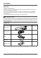
know your string trimmer 1 2 3 4 5 7 6 8 Fig.
know your string trimmer KNOW YOUR string trimmer (See Figure 1.) The safe use of this product requires an understanding of the information on the product and in this operator’s manual as well as a knowledge of the project you are attempting. Before use of this product, familiarize yourself with all operating features and safety rules. 1. BATTERY PACK LATCH Press to release the battery pack from the tool. 2. REAR HANDLE Ergonomic handle with overmold improves comfort and grip. 3.
ASSEMBLY UNPACKING This product requires assembly. • Carefully remove the product and any accessories from the box. Make sure that all items listed in the packing list are included. • Inspect the tool carefully to make sure no breakage or damage occurred during shipping. • Do not discard the packing material until you have carefully inspected and satisfactorily operated the tool. • If any parts are damaged or missing, please call 1-855-345-3934.
ASSEMBLY WA R N I N G If any parts are damaged or missing, do not operate this product until the parts are replaced. Use of this product with damaged or missing parts could result in serious personal injury. WA R N I N G Do not attempt to modify this product or create accessories not recommended for use with this string trimmer. Any such alteration or modification is misuse and could result in a hazardous condition leading to possible serious personal injury.
ASSEMBLY attaching the Guard (see Figure 3.) NOTE: Install the guard before the attachment is connected to the lower shaft. 1. 2. Invert the string trimmer to access the trimmer head. Remove supplied screws (1) from the trimmer head (4) with a philips head screwdriver (not included). 1 Fig. 3.1 3. 4. Place the guard (2) on to the trimmer head. Align the screw holes on the guard (3) with the screw holes on the trimmer head (4) 2 3 4 Fig. 3.2 5.
ASSEMBLY iNSTALLING THE UPPER SHAFT TO THE LOWER SHAFT (See Figure 4.) WA R N I N G Never install, remove, or adjust any attachment while string trimmer is running. Failure to stop the motor can cause serious personal injury. The attachment connects to the power head by means of a coupler device. 1. Set the unit on a flat, level surface. 2. Loosen the knob (1) on the coupler (5). 3. Push in the release button (2) located on the lower shaft (3).
ASSEMBLY attaching the Auxiliary handle (See Figure 5.) 1. Loosen the four screws (1) in the handle with a philips screwdriver (not included) and remove the screws from the handle. 1 Fig. 5.1 2. 3. Attach the auxiliary handle (2) and lower clamp (3) on the shaft. Adjust handle up or down, if necessary, to desired operating position. Fig. 5.2 4. Tighten the four screws so that the handle cannot be rotated on the shaft. Fig. 5.
ASSEMBLY aDJUSTING the CUTTING SWATH (See Figure 6.) This trimmer is equipped with a line cut-off blade on the guard. The line cut off blade continuously trims the line to ensure a consistent and efficient cut diameter. Advance line whenever you hear the engine running faster than normal, or when trimming efficiency diminishes. This will maintain best performance and keep line long enough to advance properly. This trimmer is currently set at the 14 in. cutting swath. To adjust to a cutting swath of 16 in.
OPERATIon WA R N I N G Read and understand entire Operator's Manual for each optional attachment used on this power head and follow all warnings and instructions. Failure to follow all instructions may result in electric shock, fire and/or serious personal injury. WA R N I N G Do not allow familiarity with this product to make you careless. Remember that a careless fraction of a second is sufficient to inflict serious injury.
OPERATIon INSTALLING THE BATTERY PACK (See Figure 7.) • Insert battery pack into tool until an audible click is heard. REMOVING THE BATTERY PACK (See Figure 7.) • Depress the battery release button (1) in the back of the battery pack and pull battery pack out of tool. 1 Fig. 7 starting and stopping the trimmer (See Figure 8.) • Ensure a fully charged battery is installed into the string trimmer. • To start the string trimmer, press and hold the safety lock button (1) and squeeze the switch trigger (2).
OPERATIon operating the trimmer (See Figure 9.) WA R N I N G Always hold the string trimmer away from the body keeping clearance between the body and the string trimmer. Any contact with the string trimmer cutting head while operating can result in serious personal injury. Follow these tips when using the string trimmer: • Hold the trimmer with your right hand on the reat handle and your left hand on the auxiliary handle. • Keep a firm grip with both hands while in operation.
OPERATIon WA R N I N G Any contact with the attachment cutting head can result in burns and/or other serious personal injury. WA R N I N G Read the safety information for safe operation when using a blade attachment and refer to the safety rules and instructions in your attachment manual. Never use a brush cutter attachment with this electric power head. Improper operation of a blade or any attachment could result in serious injury. ADVANCING LINE (See Figure 10.
OPERATIon REPLACING THE LINE (See Figure 11.) 1. Press the tabs simultaneously on the side of the trimmer head and remove cover and spool. Tab Cover Spool Fig. 11.1 2. 3. 4. Remove any remaining line. Clean dirt and debris from all parts. Replace spool if it is worn or damaged. Replace with a pre-wound spool, or replace line using 25 feet (8 meters) of 0.080 inch (2.0 mm) diameter line. WA R N I N G Never use wire, rope, string, etc., which can break off and become a dangerous projectile. 5.
OPERATIon 6. Bend the line at the midpoint and insert the bend into the slot in the center rim of the spool. Ensure line snaps into position in the slot. Slot Fig. 11.2 7. With your finger between the lines, wrap the lines evenly and firmly around the spool in a clockwise direction. Fig. 11.3 8. Position the lines in the guide slots. Fig. 11.
OPERATIon 9. Place the spool in the cover as shown below. Fig. 11.5 10. Insert the ends of the lines through the line exit holes in the sides of the cover. Fig. 11.6 11. Reinstall the spool and cover onto the trimmer head. Push until cover snaps into place. Fig. 11.
OPERATIon cutting tips (See Figure 12.) • Keep the trimmer tilted toward the area being cut; this is the best cutting area. • The trimmer cuts when passing the unit from right to left. This will avoid throwing debris at the operator. Avoid cutting in the dangerous area shown in figure 12. • Use the tip of string to do the cutting; do not force string head into uncut grass. • Wire and picket fences cause extra string wear and breakage. Stone and brick walls, curbs, and wood may wear string rapidly.
BATTERY & CHARGER MAINTENANCE CHECKING BATTERY CAPACITY Press the battery capacity indicator (BCI) button. The lights will illuminate according to the batteries capacity level.
BATTERY & CHARGER MAINTENANCE CHECKING THE CHARGE If the battery pack does not charge properly: • Check the current at the power outlet with another tool. Make sure that the outlet is not turned off. • Check that the charger contacts have not been shorted by debris or foreign material. • If the surrounding air temperature is not normal room temperature, move the charger and battery pack to a location where the temperature is between 45 ˚F and 104˚F .
MAINTENANCE general maintenance Avoid using solvents when cleaning plastic parts. Most plastics are susceptible to damage from various types of commercial solvents and may be damaged by their use. Use clean cloths to remove dirt, dust, lubricant, grease, etc. Always store the machine clean and in a dry enclosure with the battery charged.
ENVIRONMENTALLY SAFE BATTERY DISPOSAL The following toxic and corrosive materials are in the batteries used in this string trimmer battery pack: Lithium-Ion, a toxic material. WA R N I N G All toxic materials must be disposed of in a specified manner to prevent contamination of the environment. Before disposing of damaged or worn out Lithium-Ion battery packs, contact your local waste disposal agency, or the local Environmental Protection Agency for information and specific instructions.
troubleshooting Problem String trimmer fails to start when trigger lock button is depressed. Cause Solution 2. No electrical contact between the trimmer and battery. 2. Remove battery check contact and reinstall the battery pack. 1. The battery pack is not attached to the trimmer. 1. Attach the battery pack to the trimmer. 3. The battery pack is depleted. 3. Charge the battery pack. 4. The lock-off lever and trigger are not depressed simultaneously. 4.
troubleshooting Problem Lines will not advance. Cause Solution 1. Lines are welded to themselves. 1. Lubricate with silicone spray. 2. Not enough line on spool. 2. Install more line. Refer to Line Replacement earlier in this manual. 3. Lines are worn too short. 3. Pull both lines while pressing button. 4. Lines are tangled on spool. 4. Remove lines from spool and rewind. Refer to Line Replacement earlier in this manual. 1. Trimmer used incorrectly. 1.
LIMITED WARRANTY GREENWORKS™ hereby warranties this product, to the original purchaser with proof of purchase, 4 year warranty against defects in materials, parts or workmanship. GREENWORKS™, at its own discretion will repair or replace any and all parts found to be defective, through normal use, free of charge to the customer.
EXPLODED VIEW 5 4 2 3 1 6 7 8 9 10 11 12 13 30 14 15
parts list Item No. 1 2 3 4 5 6 7 8 9 10 11 12 13 14 15 Part No.
Greenworks Tools PO Box 1238 Mooresville, NC 28115 TOLL-FREE HELPLINE: 1-855-345-3934 Rev: 00 (11-25-15)
Desbrozadora inalámbrica 80V 16” ST80L00 Manual Del Propietario LÍNEA GRATUITA LÍNEA DE AYUDA: 1-855-345-3934 www.greenworkstools.com/80v-pro Leer todas las normas de seguridad y las instrucciones cuidadosamente antes de utilizar esta herramienta.
Contenidos Contenidos........................................................................................................................... 2 Especificaciones .................................................................................................................. 2 Reglas generales de seguridad............................................................................................ 3 Símbolos...................................................................................................
REGLAS GENE RALES DE SE GURIDAD A D V E R T E N C I A Lea y comprenda todas las instrucciones antes de usar este producto. Si no sigue todas las instrucciones enumeradas a continuación, podrían producirse descargas eléctricas, incendios y/o daños personales graves. • Revise el área de trabajo cada vez antes del uso. Quite todo objeto inadecuado tal como rocas, fragmentos de vidrio, clavos, alambre o cuerdas que pudieran saltar o enrollarse en la máquina.
REGLAS GENE RALES DE SE GURIDAD delequipo para jardin. • No deseche las baterías tirándolas al fuego. Las celdas podrían explotar. Verifique los códigos locales para averiguar si hay instrucciones especiales para su desecho. • No abra las baterías ni las corte. El electrolito suelto es corrosivo y podría causar lesiones en los ojos o la piel. Podría ser tóxico si se le ingiere.
SÍMBOLOS Es posible que se empleen en este producto algunos de los siguientes símbolos. Le suplicamosestudiarlos y aprender su significado. Una correcta interpretación de estos símbolos le permitirá utilizar mejor y de manera más segura el producto.
SÍMBOLOS Las siguientes palabras de señalización y sus significados tienen el objeto de explicar los niveles de riesgo relacionados con este producto. SÍMBOLO SEÑAL SIGNIFICADO PELIGRO Indica una situación peligrosa inminente, la cual, si no se evita, causará la muerte o lesiones serias. ADVERTENCIA Indica una situación peligrosa posible, la cual, si no se evita, podría causar la muerte o lesiones serias.
SEPA SU PRODUCTO 1 2 3 4 5 7 6 8 Fig.
SEPA SU PRODUCTO CONOZ CA SU PROD UCTO (Vea la figura 1.) El uso seguro de este producto requiere la comprensión de la información del producto y del manual de usuario, así como el conocimiento de la tarea que intenta realizar. Antes de utilizar este producto, familiarícese con las características de funcionamiento y normas de seguridad. 1. SEGURO DE LA BATERÍA Pulse para retirar la batería de la herramienta. 2. EMPUÑADURA TRASERA Mango ergonómico sobremoldeado para mayor comodidad y sujeción. 3.
ARMADO DESEMBALAJE Es necesario montar este producto. • Retire con cuidado el producto y los accesorios de la caja. Asegúrese de que están incluidos todos los elementos que figuran en la lista del paquete de embalaje. • Revise el producto con atención para asegurarse de que no se produjeron daños o roturas durante el transporte. • No tire el material de embalaje hasta que haya revisado con atención y haya utilizado el producto de manera satisfactoria.
ARMADO A D V E R T E N C I A Si falta alguna parte dañada o se encuentra dañada, no utilice el producto hasta que haya sustituido las piezas. Usar este producto si falta alguna pieza o si alguna está dañada podría provocar graves daños personales. A D V E R T E N C I A No intente modificar este producto o crear accesorios no recomendados para ser usados con él.
ARMADO COLOCAR EL DEFLECTOR DE HIERBA (Vea la figura 3.) NOTA: Instale el deflector de hierba antes de conectar el accesorio a la cabeza motriz. 1. 2. Invierta la orilladora para obtener acceso al cabezal de la orilladora. Retire los tornillos (1) suministrados del cabezal de corte (4) con un destornillador de estrella (no incluido). 1 Fig. 3.1 3. 4. Coloque la protección (2) en el cabezal de corte.
ARMADO INSTALAR EL EJE SUPERIOR EN EL EJE INFERIOR (Vea la figura 4.) A D V E R T E N C I A Nunca instale, retire o ajuste ningún accesorio mientras sigue funcionando el bloque motor. Un fallo en la parada del motor puede causar lesiones personales graves. El accesorio se conecta al bloque motor mediante un anillo de acople. 1. Coloque la herramienta en una superficie plana y nivelada. 2. Afloje el vástago (1) del acoplador (5). 3. Pulse el botón de liberación (2) situado en el eje inferior (3).
ARMADO FIJACIÓN DEL MANGO DELANTERO (Vea la figura 5.) 1. Afloje los cuatro tornillos (1) del mango con un destornillador de estrella (no incluido) y retire los tornillos del mango. 1 Fig. 5.1 2. 3. Acople el mango auxiliar (2) y baje la abrazadera (3) del eje. Si es necesario, suba o baje el mango para ajustarlo a la posición de manejo deseada. Fig. 5.2 4. Apriete los cuatro tornillos de manera que la empuñadura no pueda girar sobre el eje. Fig. 5.
ARMADO CUCHILLA DE CORTE DEL HILO (Vea la figura 6.) Esta recortadora está equipada con una cuchilla de corte instalada en el protección. Para obtener mejores resultados en el recorte, avance el hilo hasta que la cuchilla lo corte a la longitud apropiada. Avance el hilo siempre que escuche que el motor está funcionando más rápido de lo normal, o cuando disminuya la eficiencia del recorte. Esto mantendrá un desempeño óptimo y mantendrá el hilo a la suficiente longitud para que avance correctamente.
Funcionamiento A D V E R T E N C I A Lea y comprenda el manual de usuario en su totalidad para cada accesorio opcional utilizado en esta cabeza motriz y siga todas las advertencias e instrucciones. Si no sigue todas las instrucciones, podrían producirse descargas eléctricas, incendios y/o daños personales graves. A D V E R T E N C I A Preste especial atención aunque esté familiarizado con el producto. Recuerde que un despiste de una sola fracción de segundo es suficiente para causar daños graves.
Funcionamiento INSTALACIÓN DE LA BATERÍA (Vea la figura 7.) • Inserte la batería en la herramienta hasta que escuche un clic. EXTRACCIÓN DE LA BATERÍA (Vea la figura 7.) • Pulse el botón de liberación de la batería (1) en la parte trasera de la batería y retire la batería de la herramienta. 1 Fig. 7 ARRANCAR Y DETENER LA RECORTADORA (Vea la figura 8.) • Compruebe que hay una batería totalmente cargada instalada en la recortadora de hilo.
Funcionamiento FUNCIONAMIENTO DE LA CABEZA MOTRIZ (Vea la figura 9.) A D V E R T E N C I A Siempre sujete la recortadora de hilo lejos de su cuerpo, manteniendo un espacio entre ambos. El contacto con el cabezal de corte de la recortada de hilo durante su operación puede causar lesiones personales graves. Siga las siguientes recomendaciones a manejar la recortadora de hilo: • Sujete la recortadora con la mano derecha en el mango trasero y la izquierda en el delantero.
Funcionamiento A D V E R T E N C I A Cualquier contacto con el cabezal de corte del accesorio podría provocar quemaduras y/o lesiones personales graves. A D V E R T E N C I A Lea la información de seguridad para una utilización segura cuando use un accesorio de la hoja y consulte las normas de seguridad e instrucciones del manual de usuario. No utilice nunca un accesorio de desbrozadora con esta cabeza motriz.
Funcionamiento REEMPLAZO DE LA LINEA DE CORTE (Vea la figura 11.) 1. Presione las lengüentas en un lado del cabezal de corte y remueva la cubierta y bobina. Lengüenta Cubierta Bobina Fig. 11.1 2. 3. 4. Remueva la línea restante. Limpie la suciedad y desechos de todas las piezas. Cambie la bobina si ésta se encuentra gastada o dañada. Sustituya el carrete prebobinado o sustituya el hilo usando hilo de 25 pies (8 metros) de 0,080 pulgadas (2.0 mm) de diámetro.
Funcionamiento 5. 6. Cuando instale línea nueva en una bobina ya existente, sujete la bobina según lo demostrado en la ilustración abajo. Doble la línea en el puntomedio y inserte la parte doblada de la línea en la ranura que se encuentra en el reborde central de la bobina. Asegúrese que la línea encaje fírmemente en su lugar. Ranura Fig. 11.2 7. Con sus dedos inserte ambas líneas, enrolle las líneas firmemente al parejo alrededor de la bobina en dirección a la derecha. Fig. 11.3 8.
Funcionamiento 9. Coloque el carrete en la tapa como se muestra a continuación. Fig. 11.5 10. Inserte los extremos de las líneas a través de orificios de salida de línea en los lados de la cubierta. Hueco de salida Cubierta Fig. 11.6 11. Vuelva a instalar el carrete en el cabezal de corte. Empuje hasta que la cubierta encaje en su lugar. Fig. 11.
Funcionamiento CORTAR PUNTAS (Vea la figura 12.) • Mantenga la recortadora inclinada hacia la zona a cortar; esta es la mejor área de corte. • La recortadora corta al pasar el aparato de derecha a izquierda. Esto evitará que se arrojen desechos al operador. Evite cortar en la zona peligrosa mostrada en la figura 12. • Utilice la punta del hilo para cortar; no fuerce la cabeza para hilo de corte en la hierba no cortada. • Las vallas de madera o alambre provocan un desgaste excesivo del hilo y rotura.
MANTENIMIENTO DE LA BATERÍA Y EL CARGADOR COMPROBACIÓN DE LA PILA Pulse el indicador de capacidad de la batería (BCI). Las luces se encenderán según el nivel de capacidad de las baterías.
MANTENIMIENTO DE LA BATERÍA Y EL CARGADOR COMPROBACIÓN DE LA CARGA Si la batería no se recarga adecuadamente: • Compruebe la corriente de la toma con otro aparato eléctrico. Asegúrese de que la toma está encendida. • Compruebe que no haya residuos ni elementos extraños interfiriendo en las conexiones del cargador. • Si la temperatura del aire es mayor que 100°F (37.77°C) o menor que 45°F (7.2°C), coloque el cargador y la batería en un lugar que esté a temperatura ambiente.
MANTENIMIENTO MANTENIMIENTO GENERAL Evite el uso de disolventes para limpiar las piezas de plástico. La mayoría de los plásticos son susceptibles a diversos tipos de disolventes comerciales y pueden dañarse por su uso. Utilice paños limpios para eliminar la suciedad, el polvo, los restos de lubricante y grasa, etc. Guarde siempre la máquina limpia y en un recinto seco, con la batería cargada.
ELIMINACIÓN DE BATERÍAS SIN DAÑO PARA EL AMBIEN TE Las baterías utilizadas en este cortasetos contienen los siguientes materiales tóxicos y corrosivos: Litio-ión, un material tóxico. A D V E R T E N C I A Todos los materiales tóxicos deben ser desechados de forma específica para evitar contaminar el medio ambiente.
SOLUCIÓN DE PROBLEMAS Problema La recortadora de hilo no puede arrancarse cuando el botón de bloqueo del gatillo está pulsado. La recortadora de hilo se detiene durante el corte. Causa 1. La batería no está instalada en la recortadora. Solución 1. Instale la batería en la recortadora. 2. No hay contacto eléctrico entre la recortadora y la batería. 2. Retire la batería, compruebe el contacto y vuelva a instalar la batería. 3. La batería está agotada. 3. Cargue la batería. 4.
SOLUCIÓN DE PROBLEMAS Problema Las líneas no avanzan. El hilo sigue rompiéndose. La hierba se enrolla alrededor del cabezal de corte y de la cubierta del motor. El hilo no corta bien. Causa Solución 1. Los hilos están soldados entre sí. 1. Lubrique con espray de silicona. 2. No hay suficiente hilo en el 2. Instale cable extra. Consulte el apartado carrete. "Sustitución de la línea", que aparece anteriormente en este manual. 3. Los hilos son demasiado 3.
GARANTÍA LIMITADA Por este medio y por un período de cuatro años GREENWORKS™ garantiza este producto contra defectos en materiales, piezas o mano de obra al comprador original que cuente con una prueba de compra. GREENWORKS™, a su sola discreción reparará o reemplazará, sin costo algun o para el cliente, cualquier pieza defectuosa, siempre y cuando se haya hecho uso normal de ella.
PLANO DE DESPIECE 5 4 2 3 1 6 7 8 9 10 11 12 13 30 14 15
LISTA DE PIEZAS N.º Pieza 1 2 3 4 5 6 7 8 9 10 11 12 13 14 15 N.º Modelo 34107511-10 311121416 33208334 34130334 34140334 333041429 332041428 341041429AB 311101429 311091429 322011429 32207319 32916131 333011429 341081429AB Descripción Perilla Conjunto de herramienta Bare Tornillo Mango auxiliar Placa Guía de bordes Primavera Perilla del golpeador Bobina Cubierta del carrete Arandela Tornillo Arandela Cuchilla de corte Protector 31 Cant.
Greenworks Tools PO Box 1238 Mooresville, NC 28115 LÍNEA GRATUITA LÍNEA DE AYUDA: 1-855-345-3934 Rev: 00 (11-25-15)