E39.0.31.6C-02 Data logger for as of version V1.0 Operating Manual humidity temperature T-Logg 160 GREISINGER electronic GmbH D - 93128 Regenstauf, Hans-Sachs-Straße 26 +49 (0) 9402 / 9383-0 +49 (0) 9402 / 9383-33 info@greisinger.
E39.0.31.6C-02 1 Operating instruction T-Logg 160 page 2 of 8 General The logger T-Logg 160 is designed as a cost-efficient solution for monitoring humidity and temperatures. It enables an individual programming of the recording time. The last 16,000 measuring values can be stored in the memory. In addition, the LCD-display indicates both the temperature measured at the moment and the operating status of the logger.
E39.0.31.6C-02 4 Operating instruction T-Logg 160 page 3 of 8 Connection ■ Assignment of the input jack (front view to the pins): Interface [–] Not connected Interface [+] 5 Advice regarding state of logger upon delivery: Upon its delivery the logger is in a kind of 'sleeping state': The display does not show anything, the power consumption is at its minimum. The T-Logg ‘wakes up’ as a communication link with a software has been established. After that the message ‘Stop‘ appears at display.
E39.0.31.6C-02 Operating instruction T-Logg 160 page 4 of 8 BATTERY: • Changing display BAT / Value: The battery of the T-Logg is getting discharged soon. Replace the battery briefly. Even so data logging is still active. • Constant display BAT: The Logger battery is empty now and data logging has been stopped. Replace the battery immediately. ALARM LOW: The measured value (unit arrow points to the concerned measuring) is below the min. alarm limit.
E39.0.31.6C-02 8 Operating instruction T-Logg 160 page 5 of 8 Battery replacement Notice: As soon as BAT appears at display, the battery needs to be replaced. If battery voltage power decreases continuously, data logging will be stopped (compare with operating status ‘HALT’). Available stored data remains in the memory and do not get lost. It’s possible to read the measuring data after replacement of the battery.
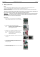
E39.0.31.6C-02 Operating instruction T-Logg 160 7. Insert the new button cell (type CR 2032) with correct polarity in the socket (the positive pole is on the retaining bracket). 8. Induct the sensor connection into the hole of the probe tube and put the board into the housing. 9. Thread the foam rubber onto the connector again and move it back into the probe tube. 10. Plug the sensor element to the connector (mind right mounting position).
E39.0.31.6C-02 9 Operating instruction T-Logg 160 page 7 of 8 Specification: Measuring range: humidity: temperature: 0.0 … 100.0 %RH (rec. operating range: 10 – 90 %RH) -25.0 … +60.0 °C Resolution: 0.1 %RH and 0.1 °C (display and memory) Accuracy: (at nominal temperature) humidity: ≤ ±3 %RH (at range 10 – 90 %RH) temperature: ± 0.3 °C ± 0.017 * (T - 25°C) Sensor: mounted in sensor tube Display: LCD display, 10 mm high, 4-digit Recording interval: 4s to 5h Measuring value memory: 16.
E39.0.31.
S58.0.01.6C-01 T-Log gg USB level converter Installation-- and operating manual U USB 100 GRE EISINGER electronic GmbH G D - 93128 Regenstauf, Hans-Sachs-S Straße 26 Tel.: +49 9402 / 9383-0, Fax: +49 9402 / 9383-33, eMail: info@greisinger.
S58.0.01.6C-01 Page 2 of 6 Content 1. Intended use.............................................................................................................................................................. 3 2. General advice........................................................................................................................................................... 3 3. Safety instructions ................................................................................................
S58.0.01.6C-01 Page 3 of 6 1. Intended use The level converter enables the connection of T-Logg module to the USB-interface of your PC. Applications: • Exchange data capture • Configuration of T-Logg function • Readout measuring data storage etc. 2. General advice Read through this document attentively and make yourself familiar to the operation of the device before you use it. Keep this document in a ready-to-hand way in order to be able to look up in the case of doubt. 3.
S58.0.01.6C-01 Page 4 of 6 5. Installation 5.1 Windows Vista™, Windows XP and Windows 2000 For installation of the device drivers a user account with an administrator-authorisation is required. If you haven’t an appropriate authorisation please consult your system administrator. • Insert driver cd into the drive of your PC. • Start the installation of the driver. Path-example: E:\Treiber USB100\CDM 2.02.04.exe E: means the letter of your drive. • Follow the instructions of installation.
S58.0.01.6C-01 Page 5 of 6 7. Frequently asked questions (FAQ) 7.1 How to check whether the adaptor has been installed correctly and via which COMport can I approach the installed adaptor? Start the Device-Manager: start \ settings \ control panel \ performance and maintenance \ system \ hardware and open the submenu “Ports (COM & LPT)” If the installation was successful, there will be the entry“USB Serial Port (COM x)”, in which the x after the Com indicates the available COM-port (i.e. COM 3).
S58.0.01.
Operating Manual MINISOFT as of Version 7.11 CONTENTS 1 GENERAL ADVICE................................................................................................................................................................. 1 2 INSTALLATION AND COMMISSIONING ......................................................................................................................... 2 3 OPERATION OF LOGGERS WITH MINISOFT – STEP BY STEP ................................................................
G14.0.11.6C-04 Operating Manual MINISOFT page 2 2 Installation And Commissioning Software Installation - start Windows place CD in CD-ROM disk drive start ‚minisoft_v7_8_setup.exe‘ - file or your available version continue in accordance with the instructions given by the installation program Starting the Software The software can be started by clicking on the ‚MINISOFT‘ icon.
G14.0.11.6C-04 Operating Manual MINISOFT page 3 Step 3: Start New Logger Recording To start a new logger recording select ‘Start New Logger Recording’ from the ‘Logger’ menue. (Unless you have already done so: link to connected loggers, see above). Note: Data that have already been recorded will be lost after a new logger recording has been started! Read the logger data and save them into a file, if necessary! (p.r.t. step 6) Alarm limits and identification will have to be entered prior to the start (p.
G14.0.11.6C-04 Operating Manual MINISOFT page 4 4 The Logger Window – In Details You have a choice between 5 different registers: • Device (not available if logger window has been read from file) • Read Data (or Data, if logger window has been read from file) • Comment • Settings • About Headlines displayed above the registers: - Window title (can be edited in register ‘Settings’) - logger serial number and type 4.
G14.0.11.6C-04 Operating Manual MINISOFT page 5 4.4 Settings Display of all the editable properties and settings of the logger. Please note: If the logger contains recorded data the settings can only be changed if the data are deleted!! The Window Title can be edited here Identification (up to 16 digits, older logger types do not support an identification, ‚--‘ will be displayed then) The identification is displayed at the top of the logger window and will help you to identify the logger.
G14.0.11.6C-04 Operating Manual MINISOFT page 6 6 Measuring Value Diagrams The logger data and logger windows loaded can also be displayed as diagrams. To do so select ‘Create New Diagram‘ from the ‘Diagram’ menue. A selection of all possible graphs will be displayed. Select the graphs desired and acknowledge selection by pressing ‘Ok’. The diagram will be opened. System limitations: - max. 2 different units (°C, %RH, etc.) per diagram - max.
G14.0.11.6C-04 Operating Manual MINISOFT page 7 7 How to Print Data The selected window (logger window with data or diagram) can be printed via ‘File – Print’ provided a printer has been installed to the computer. Use ‘File – Printer Setup’ to change printer parameters or to chose another printer. If the diagram is not printed: for some types of graphics cards it may happen that the diagram will not be printed if the color depth is set to 16 bit.
G14.0.11.6C-04 Operating Manual MINISOFT page 8 Configuration Of a Remote Logger Connection: When configuring a remote logger connection there has to be entered a random label (or name) at the point ‚Remote Logger Connection‘ and the phonenumber of the industry modem at which the loggers are connected. This industry modem has to be a specialized device, adopted to the EASYBUS data transfer (e.g. MODEM 1000, 2000 HS, IAM 80 or 3000 GSM).