
User manual


E44.X.00.6C-02 Connection and operating manual GIR 300 page 3 of 28
1 General Note
Read this document carefully and get used to the operation of the device before you use it.
Keep this document within easy reach near the device for consulting in case of doubt.
Mounting, start-up, operating, maintenance and removing from operation must be done by qualified, specially trained
staff that have carefully read and understood this manual before starting any work.
The manufacturer will assume no liability or warranty in case of usage for other purpose than the intended one, ig-
noring this manual, operating by unqualified staff as well as unauthorized modifications to the device.
The manufacturer is not liable for any costs or damages incurred at the user or third parties because of the usage or
application of this device, in particular in case of improper use of the device, misuse or malfunction of the connection
or of the device.
The manufacturer is not liable for misprints.
2 Intended Use
The GIR 300 is a microprocessor controlled displaying, monitoring and controlling device..
The device is supporting one universal interface for the connection of:
- Standard transmitter signals (0-20 mA, 4-20 mA, 0-50 mV, 0-1 V, 0-2 V
and 0-10 V),
- RTD (Pt 100 and Pt 1000),
- Thermocouple probes (type K, J, N, T and S)
- Frequency (TTL and switching contact)
As well as rotation measuring, counting, etc...
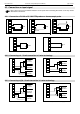
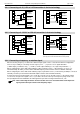
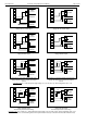
The device features two switching outputs, which can be configured as 2-point-controller, 3-point-controller, 2-point-
controller with min./max. alarm, common or individual min./max. alarm.
The state of the switching contacts is displayed with 2 LED´s. LED “1” displays the state of the contact of relay 1 and
LED “2” displays the state of contact of relay 2. (LED illuminate = contact is closed)
Furthermore the device supports one EASYBus -interface for communicating with a host computer that makes the
device to a full functions EASYBus-module.
When leaving our factory the GIR 300 has been subjected to various inspection tests and is completely calibrated.
Before the GIR 300 can be used, it has to be configured for the customer’s application.
Hint: In order to avoid undefined input states and unwanted or wrong switching processes, we suggest
to connect the device’s switching outputs after You have configured the device properly.
Hint: By calling a configuration menu (configuration of the measuring input, configuration of the output
function, offset- and slope-adjustment) the measurement and regulation of the device will be deac-
tivated.
By leaving the menu the device will be reinitialised and the measuring/regulation will be started
again.
At the input function “counter” the counter state will be reset by leaving the menu.