
User manual


E44.X.00.6C-02 Connection and operating manual GIR 300 page 5 of 28
4 Electric connection
Wiring and commissioning of the device must be carried out by trained and skilled personnel only.
Wrong connection may lead to the destruction of the display device, in which case we cannot assume any
warranty!
! Mind for the maximum input conditions !
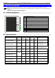
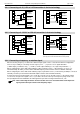
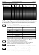
4.1 Terminal assignment
1
EASYBus-Interface
2
EASYBus-Interface
3
Input: 0-10V
4
Input: 0-50mV, thermocouples, Pt100
5
Input: 0-1V, mA, frequency, Pt100, Pt1000
6
Input: GND, Pt100, Pt1000
7
Power supply GND
8
Power supply +Uv
9
Output 2: relay, break contact
10
Output 2: relay, input
11
Output 1: relay, input
12
Output 1; relay, make contact
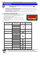
4.2 Connection data
between
terminals
typical
limitations
Note
min.
max.
min.
max.
Power supply voltage
7 and 8
9
28
0
30
or corresponding designation
on the type plate
Output 1:
relay: make contact
11 and 12
253 VAC
5A
ohmic load
or corresponding designation
on the type plate
Output 2
relay: break contact
9 and 10
253 VAC
5A
ohmic load
or corresponding designation
on the type plate
Input 0-50mV, TC, ...
4 and 6
0 V
3.3 V
-1 V
10 V,
I<10mA
Input mA
5 and 6
0 mA
20 mA
0 mA
30 mA
Input 0-1(2)V, freq., ...
0 V
3.3 V
-1 V
30 V,
I<5mA
Input 0-10V
3 and 6
0 V
10 V
-1 V
20 V
Input Pt100 (Pt1000)
4, 5 and 6
0 Ω
∞ Ω
active signal not allowed
EASYBus-Interface
1 and 2
12 V
36 V
0 V
42 V
These limits must not be exceeded (not even for a short time)!
12
10