
User manual


E44.X.00.6C-02 Connection and operating manual GIR 300 page 6 of 28
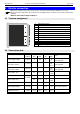
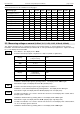
4.3 Connection an input signal
Please take care not to exceed the limitations of the inputs when connecting the device as this may lead to
destruction of the device.
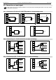
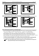
4.3.1 Connection a Pt 100 or Pt 1000 RTD probe or a thermocouple probe
Pt100
6
5
4
Pt100
6
5
4
Pt100
6
5
4
Pt100-RTD probe (3-wire)
Pt100- RTD probe (2-wire)
Pt100- RTD probe (4-wire)
Pt1000
6
5
-
+
TC
6
4
Pt1000- RTD probe (2-wire)
Thermocouple probe
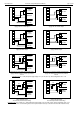
4.3.2 Connecting a 4 - 20 mA transmitter in 2-wire-technology
_
+
9-28 VDC
Supply:
-Uv
+Uv
Transmitter
4-20mA
_
+
for transmitter
Supply:
8
7
6
5
_
+
9-28 VDC
Supply:
-Uv
+Uv
Transmitter
4-20mA
8
7
5
with individual transmitter supply
without separate transmitter supply
4.3.3 Connecting a (0)4 - 20 mA transmitter in 3-wire-technology
_
+
9-28 VDC
Supply:
-Uv
Sig.
+Uv
Transmitter
0(4)-20mA
_
+
for transmitter
Supply:
8
7
6
5
_
+
9-28 VDC
Supply:
-Uv
Sig.
+Uv
Transmitter
0(4)-20mA
8
7
5
with individual transmitter supply
without separate transmitter supply
set link
non-connected