
User manual


E44.X.00.6C-02 Connection and operating manual GIR 300 page 8 of 28
_
+
9-28 VDC
Supply:
-Uv
Sig.
+Uv
Transducer
_
+
for transducer
Supply:
8
7
6
5
_
+
9-28 VDC
Supply:
-Uv
Sig.
+Uv
Transducer
8
7
5
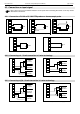
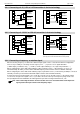
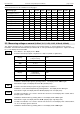
Connection of a transducer (with separate power
supply) with TTL or PNP output
Connection of a transducer (without separate power
supply) with TTL or PNP output
_
+
9-28 VDC
Supply:
-Uv
Sig.
+Uv
Transducer
_
+
for transducer
Supply:
8
7
6
5
_
+
9-28 VDC
Supply:
-Uv
Sig.
+Uv
Transducer
8
7
5
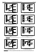
Connection of a transducer (with separate power
supply) with NPN output
Connection of a transducer (without separate power
supply) with NPN output
_
+
9-28 VDC
Supply:
Rv
-Uv
Sig.
+Uv
Transducer
_
+
for transducer
Supply:
8
7
6
5
_
+
9-28 VDC
Supply:
Rv
-Uv
Sig.
+Uv
Transducer
8
7
5
Connection of a transducer (with separate power
supply) with NPN output and necessary external
resistor
Connection of a transducer (without separate power
supply) with NPN output and necessary external
resistor
Connection note: Rv = 3 kΩ (with power supply voltage =12 V) or 7 kΩ (at 24 V), device configuration: Sens = TTL
_
+
9-28 VDC
Supply:
Rv2
Rv1
-Uv
Sig.
+Uv
Transducer
_
+
for transducer
Supply:
8
7
6
5
_
+
9-28 VDC
Supply:
Rv2
Rv1
-Uv
Sig.
+Uv
Transducer
8
7
6
5
Connection of a transducer (with separate power
supply) with PNP output
and necessary external resistor wiring.
Connection of a transducer (without separate power
supply) with PNP output
and necessary external resistor wiring.
Connection note: Rv2 = 600Ω, Rv1 = 1.8kΩ (with power supply voltage =12V) or 4.2kΩ (at 24V), device configuration: Sens = TTL
(Rv1 is a current limiting resistor and may be shorted if necessary. It should never exceed the mentioned value)