
User manual


E44.X.00.6C-02 Connection and operating manual GIR 300 page 9 of 28
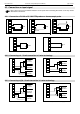
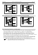
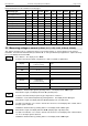
4.3.7 Connecting a counter signal
When configuring the device you can select 3 different input signal modes similar to the connection of frequency-
and rotation-signals.
The connection of a sensor-signal for a counter-signal is the same used for the frequency- and rotation-signal.
Please use the wiring diagram given in this chapter.
There is the possibility to reset the counter. When connecting contact 4 with GND (e.g. contact 6) the counter will
be reset. You can do this manually (e.g. with the help of a push-button) or automatically (with one switching out-
put of the device).
Hint: When connecting the device, take care not to exceed the limits of the input-voltage or the input-
current of the frequency input.
_
+
9-28 VDC
Supply:
-Uv
Sig.
+Uv
transducer
Impulse
8
7
6
5
4
Reset-
button
-Uv
Sig.
+Uv
transducer
Impulse
_
+
9-28 VDC
Supply:
no.2
device
8
7
5
no.1
device
12
11
8
7
5
4
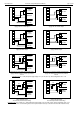
Manually reset the device
with the help of an push-button
_
+
9-28 VDC
Supply:
-Uv
Sig.
+Uv
transducer
Impulse
12
11
8
7
6
5
4
Reset-
button
automatically resetting with the help of output 1 and
additional resetting the device via push-button
Connection note: output 2 can only be used to
switching of low voltage potential!
Cascading of GIR 300
(Configuration note for the GIR 300:
device 1 – input signal like impulse transducer
device 2 – input signal = switching-contact