
User manual


E44.X.00.6C-02 Connection and operating manual GIR 300 page 10 of 28
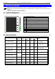
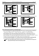
4.4 Connecting switching outputs
Hint: In order to avoid unwanted or wrong switching processes, we suggest to connect the device’s
switching outputs after you have configured the device’s switching outputs properly.
The device features 2 switching outputs by default
• output 1: relay, make contact
• output 2: relay, break contact
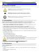
Please take care that you must not exceed the limits of the voltage and of the maximum current of
the switching outputs (not even for a short period of time).
Please take extreme care when switching inductive loads (like coils or relays, etc.). Because of
their high voltage peaks, protective measures (e.g. RC-element) to limit these peaks have to be
taken.
Note: You will find detailed information to the switching states of the different output functions in chapter 6
(“Switching points and alarm-boundaries“)
Note: In case of configuring one output as an alarm output, the relay contact will be closed at the idle state (no
alarm is present). If an alarm condition will occurred the relay contact will be opened.
(for detailed information please refer the notes in chapter 6.2 and 6.3)
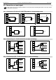
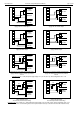
4.5 Common wiring of several devices
The input of the device are not electrically isolated to the power supply.
When interconnecting several device`s you have to make sure that there is no potential displacement
Make sure to observe the following points:
- When several devices are connected to the same power supply unit it is highly recommended to isolate the sensors,
measuring transducers etc.
- When the sensors, measuring transducers etc. are electrically connected, and you can’t manage to isolate them, you
should use separate electrically isolated power supply units for each devices.
Please note, that an electric connection may also be created via the medium to be measured (e.g. pH-electrodes
and conductivity-electrodes in fluids).