
User manual


E44.X.00.6C-02 Connection and operating manual GIR 300 page 16 of 28
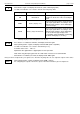
on.rG
Active, (displays the selected limit)
The measuring range is exactly bounded by
the selected frequency-measuring-range-limit.
When exceeding or shortfalling of the limit the
device will display the lower or upper display-
range-limit.
[e.g. for humidity: when shortfalling or exceed-
ing the device will display 0% or 100%]]
Hint: When exceeding the maximum range limit (10 kHz) independently from the limit setting an error message
will be displayed (“Err.1“).
- Press button 1 to validate your selection. The display shows “Li“ again.
- When pressing button 1 again, the display will show “FiLt“ (Filter = digital filter).
- Use button 2 and button 3 to select the desired filter value [in sec.].
Usable values: 0.01 ... 2.00 sec.
Explanation: this digital filter is a digital replica of a low pass filter.
- Press button 1 to validate your selection. The display shows “FiLt“ again.
Now your device is adjusted to your signal source. The only thing you left do is to adjust the outputs of the device.
- When pressing button 1 again, the display will show “outP“. (Output)
For configuring the outputs of the device, please follow the instructions shown in chapter 5.8.
5.5 Measuring of rotation speed (TTL, switching-contact)
This chapter describes how to configure the device for measuring rotation speed.
This instruction demands that you selected “rPn“ as your desired input type like it is explained in chapter 5.1.
The device has to display “InP“.
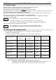
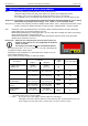
- When pressing button 1 the display will show “SEnS“.
- Use button 2 or button 3 (middle or right button) to select the desired input signal.
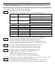
Display
Input signal
Notes
ttL
TTL-signal
nPn
Switching contact, NPN
For direct connection of a passive switching
contact (e.g. push button, relay) or Transmitter
with NPN output.
A pull-up-resistor is internally connected.
Hint: when using push-buttons or relays, they
must be bounce-free!
PnP
Switching contact, PNP
For direct connection of a transmitter with
PNP output.
A pull-down-resistor is internally connected.
Hint: For the connection of a frequency-transmitter, please follow the instructions given in chapter 4.3.6.
When connecting a switching-contact-transmitter with increased frequency range (= with external
circuitry) you have to select TTL as your desired input signal.
- Validate your selected input signal by pressing button 1. The display shows “SEnS“ again.
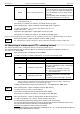
- When pressing button 1 again, the display will show “diu“ (divisor).
- Use button 2 and 3 to select your desired divisor.
Set the divisor to the pulses per rotation the transmitter supplies.
- Press button 1 to validate your selection. The display shows “diu“ again.
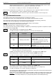
- When pressing button 1 again, the display will show “dP“ (decimal point).
- Use button 2 and button 3 to select the desired decimal point position.
Use the decimal point position to change the resolution of your measurement.
The more the decimal point position is on the left, the finer the resolution will become. Please note
that you lower the maximum value that can be displayed, either.
Example: your engine runs with 50 rotations per minute.
With no decimal point the device will display something like 49 – 50 – 51, the maximum value that can
be displayed is 9999 rotations per minute.
F,LT
SENS
OVTP
D,V
DP