
User manual


E44.X.00.6C-02 Connection and operating manual GIR 300 page 18 of 28
Example 2: Your transmitter is supplying about 5 000 000 pulses during the measurement, which ex-
ceeds the limit of the device.
But when setting a pre-scaling factor of 1000 only every 1000th pulse is used for further
processing. So you only got a value 5000 which won’t exceed the limit of the device.
- Press button 1 to validate your selection. The display shows “diu“ again.
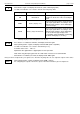
- Press button 1 again. The display shows “Co.Hi“ (counter high = upper counting range limit).
- Use button 2 and button 3 to select the maximum pulse-count (after pre-scaling factor) for the count-
ing process.
Example: Your flow rate transmitter is supplying 1800 pulses per litre, you selected a pre-scaling factor
of 100 and you are expecting a maximum flow rate of 300 litres during the measurement.
With a pre-scaling factor of 100 selected, you will get 18 pulses per litre.
With a maximum flow rate of 300 litres you will be getting a pulse count of 18 * 300 = 5400.
- Press button 1 to validate your selection. The display shows “Co.Hi“ again.
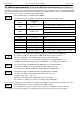
- When pressing button 1 again, the device will be displaying “dP“ (decimal point).
- Use button 2 and button 3 to select the desired decimal point position.
- Press button 1 to validate your selected decimal point position. The display shows “dP“ again.
- Press button 1 again. The display shows “di.Hi“ (display high = upper display range limit).
- Use button 2 and button 3 to set the value to be displayed when the maximum pulse (setting of co.Hi)
count is reached.
Example: Your flow rate transmitter is supplying 1800 pulses per litre and you are expecting a maxi-
mum flow rate of 300 litres. You selected a pre-scaling factor of 100 and a counter range
limit of 5400.
When wanting a resolution of 0.1 litres shown in the display of the device you would have to
set the decimal point position to ---.- and a display range limit of 300.0.
- Press button 1 to validate your selection. The display shows “di.Hi“ again.
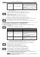
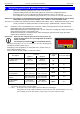
- Press button 1. The display will show “Li“ (Limit = measuring range limit).
- Use button 2 and button 3 to select the desired measuring range limit (counter range limit.
Display
Measuring range limit
Notes
off
Inactive
Exceeding of the counter range is tolerable
until you reach the maximum measuring
range limit.
on.Er
active, (error indicator)
The measuring range is exactly bounded by
the selected counter-range-limit. When ex-
ceeding or shortfalling of the limit the device
will display an error message.
on.rG
active, (measuring range limit)
The measuring range is exactly bounded by
the selected counter-range-limit. When ex-
ceeding or shortfalling of the limit the device
will display the upper counter-range-limit or 0.
Hint: The lower counter-range-limit (for configured downwards counter) is fixed to 0.
- Press button 1 to validate your selection. The display shows “Li“ again.
Now your device is adjusted to your signal source. The only thing left to do is to adjust the outputs of the device.
- When pressing button 1 again, the display will show “outP“. (Output)
For configuring the outputs of the device, please follow the instructions shown in chapter 5.8.
OVTP
DP
(O.K,
D,.K,
L,