
User manual


E44.X.00.6C-02 Connection and operating manual GIR 300 page 21 of 28
6 Switching points and alarm-boundaries
Note: All relevant switching and alarm points can be set at this menu.
(Preferred output position and delay of the output can only be set at configuration menu)
Depending on the selected output function different parameters have to be adjusted.
The configuration menu automatically skips parameters not needed for the selected output function.
Please note: The settings of the switching points and alarm-boundaries will automatically be reset to factory
default when any changes for the settings “InP”, “SEnS“ or “Unit“ had been made!
General note: The state of the switching contacts is displayed with 2 LED´s. LED “1” displays the state of the contact
of relay 1 and LED “2” displays the state of contact of relay 2. (LED illuminate = contact is closed)
Hint: The buttons 2 and 3 are featured with a ‘roll-function‘. When pressing the button once the value will be
raised (button 2) by one or lowered (button 3) by one.
When holding the button pressed for longer than 1 sec. the value starts counting up or down, the counting
speed will be raised after a short period of time.
The device also features a ‘overflow-function‘, when reaching the upper limit of the range, the device
switches to the lower limit, vice versa.
Please note: When you are configuring the device and don’t press any
button for more than 60 sec. the configuration of the device
will be cancelled.
The changes you made will not be saved and will be lost!
- When pressing button 1 for >2 sec. the menu to select the switching points
and alarm-boundaries will be called.
- Depending on the configuration you have made in the „output“ menu you
will get different Display values.
Please follow the specific chapter for further information.
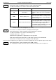
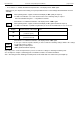
Description
Function
To select as
output
proceed in chapter
Output 1
Output 2
No output, device is used
as display unit
inactive
(contact is open)
inactive
(contact is open)
no
--
2-point-controller
switching function 1
(active = contact closed)
switching function 1
(active = contact is open)
2P
6.1
3- point-controller
switching function 1
(active = contact closed)
switching function 2
*1
(active = contact closed)
3P
6.1
2- point-controller with
min-/max-alarm
switching function 1
(active = contact closed)
min-/max-alarm
(alarm = contact closed)
2P.AL
6.2
min-/max-alarm,
common
min-/max-alarm
(alarm = contact is open)
min-/max-alarm
(alarm = contact closed)
AL.F1
6.3
min-/max-alarm,
individual
*2
max-alarm
(alarm = contact closed)
min-alarm
(alarm = contact closed)
AL.F2
6.3
*1
= Please take notice, that output 2 is a breaking contact of the relay, which means, that the contact will be
closed if the device have no power supply!
2
= Note: please take notice, that output 1 and 2 has different contact types.
Through this the device will have different contact states by max- and min-alarm in case of no
power supply is present! (Max alarm = contact is open, min alarm = contact is closed)
button 1 button 2 button 3