
User manual

E44.X.00.6C-02 Connection and operating manual GIR 300 page 23 of 28
- When pressing button 1 again, the device will be displaying “A.dEL“. (delay of the alarm-function)
- Use button 2 and button 3 to set the desired delay of the alarm-function.
Note: The unit of the value to be set [0 .. 9999] is in seconds. The device will turn on the alarm after
the minimum or maximum alarm value was active for the delay-time you have set.
- Press button 1 to validate the delay time. The display shows “A.dEL“ again.
Example: You want to have an alarm monitoring for the cooling chamber mentioned above. The
alarms should start when the temperature will be rising above -15°C or falling below -30°C.
Therefore you have to select -15°C for the maximum alarm-value “Al.Hi“ and -30°C for the
minimum alarm-value “AL.Lo“.
=> The alarm will be starting after the temperature rises above -15°C and stays above
-15°C for the entered delay time or after it had been falling below -30°C and stays
below -30°C for the entered delay time.
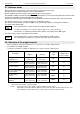
Please note: The relay for alarm output (output 2) will be active if no alarm are exist. If a alarm condition will oc-
curred the relay will drop. For this function follows the following output states:
• no alarm relay contact is open
• alarm relay contact is closed
• power failed relay contact is closed
Now you finished configuring your device. Press button 1 to switch over to display the measuring value.
6.3 Minimum/maximum alarm (individual or common)
This chapter describes how to configure the device‘s alarm boundaries for min-/max-alarm-monitoring.
This instruction demands that you selected “AL.F1“ or “AL.F2“ as your desired output function like it is explained in
chapter 5.8.
- Press button 1 (when not already done) , the device will be displaying “AL.Hi“. (maximum alarm-value)
- Use button 2 and button 3 to set the desired value, the device should turn on its maximum-alarm.
- Press button 1 to validate your selection. The display shows “AL.Hi“ again.
- When pressing button 1 again, the device will be displaying “AL.Lo“. (minimum alarm-value)
- Use button 2 and button 3 to set the desired value, the device should turn on its minimum-alarm
- Press button 1 to validate your selection. The display shows “AL.Lo“ again.
- When pressing button 1 again, the device will be displaying “A.dEL“. (delay of the alarm-function)
- Use button 2 and button 3 to set the desired delay of the alarm-function.
Note: The unit of the value to be set [0 .. 9999] is in seconds. The device will turn on the alarm after
the minimum or maximum alarm value was active for the delay-time you have set.
- Press button 1 to validate the delay time. The display shows “A.dEL“ again.
Example: You want to have a temperature alarm-monitoring of a greenhouse. The alarm should start
when the temperature rises above 50°C or falls below 15°C.
Therefore your settings will be 50°C for the maximum alarm-value “AL.HI“ and 15°C for the
minimum alarm-value “AL.Lo“.
=> The alarm will be starting after the temperature rises above 50°C and stays above 50°C
for the entered delay time or after it had been falling below 15°C and stays below 15°C
for the entered delay time.
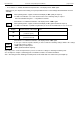
Please note: When using the output function AL.F1 (common min-/max-alarm) both outputs will be active parallel.
In consequence of the different contact types of the relay´s are both output contact states available.
output 1 output 2
• no alarm relay contact is closed relay contact is open
• alarm relay contact is open relay contact is closed
• power fail relay contact is open relay contact is closed
Please note: When using the output function AL.F2 (individual max and min alarm) the outputs have following
states:
• no alarm relay contact is open
• alarm relay contact is closed
• power fail relay contact is open (at output 1)
relay contact is closed (at output 2)
Now you finished configuring your device. Press button 1 to switch over to display the measuring value.
A.DEL
AL.K,
AL.LO
A.DEL