
User manual

E44.X.00.6C-02 Connection and operating manual GIR 300 page 24 of 28
7 Offset- and slope-adjustment
The offset and slope-adjustment function can be used for compensating the tolerance of the used sensor, and for
vernier adjustment of the used transducer or transmitter.
Please note: The settings of the offset- / slope-adjustment will be cancelled, when no button was pressed
for more than 60 sec.
Changes you may have made already won‘t be saved and will be lost!
Please note: The settings of the offset- / slope-adjustment and alarm-boundaries will automatically be reset to
factory default when any changes for the settings “InP”, “SEnS“ or “Unit“ had been made!
Hint: The buttons 2 and 3 are featured with a ‘roll-function‘. When pressing the button once the value will be raised (button 2)
by one or lowered (button 3) by one.
When holding the button pressed for longer than 1 sec. the value starts counting up or down, the counting speed will be
raised after a short period of time.
The device also features a ‘overflow-function‘, when reaching the upper
limit of the range, the device switches to the lower limit, vice versa.
- Turn on the device and wait after it finished its built-in segment test.
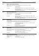
- Press button 3 > 2 sec.
The device will be displaying “OFFS“ (offset).
- Use button 2 and button 3 for setting the desired zero point
offset-value.
The input of the offset will be in digit or °C/°F.
The value that had been set will be subtracted from the measured value. (see below for further information)
- Press button 1 to validate your selection. The display shows “OFFS“ again.
- When pressing button 1 again, the device will be displaying “SCAL“. (scale = slope)
- Use button 2 and button 3 to select the desired slope-adjustment.
The slope adjustment will be entered in %. The value displayed can be calculated like this:
Displayed value = (measured value – zero point offset) * (1 + slope adjustment [% / 100] )
Example: The setting is 2.00 => the slope has risen 2.00% => slope = 102%. When measuring a value of 1000
(without slope-adjustment) the device would display 1020 (with slope adjustment of 102%).
- Press button 1 to validate the selection of the slope-adjustment. The display shows “SCAL“ again.
Now you finished the offset and slope adjustment of your device. Press button 1 to switch over to display the measur-
ing value.
Examples for offset- and slope-adjustment:
Example1: Connecting a Pt1000-sensor (with an offset error depending on the cable-length of the sensor)
The device displays the following values (without offset- or slope-adjustment): 2°C at 0°C and 102°C at 100°C
Therefore you calculated: zero point: 2
slope: 102 – 2 = 100 (deviation = 0)
You have to set: offset = 2 (= zero point-deviation)
scale = 0.00
Example2: Connecting of a 4-20mA-pressure-transducer
The device displays the following values (without offset- or slope-adjustment): 0.08 at 0.00 bar and 20.02 at 20.00 bar
Therefore you calculated: zero point: 0.08
slope: 20.02 – 0.08 = 19.94
deviation: 0.06 (= target-slope – actual slope = 20.00 - 19.94)
You have to set: offset = 0.08 (= zero point-deviation)
scale = 0.30 (= deviation / actual slope = 0.06 / 19.94 = 0.0030 = 0.30% )
Example3: Connecting of a flow-rate-transducer
The device displays the following values (without offset- or slope-adjustment): 0.00 at 0.00 l/min and 16.17 at 16.00 l/min
Therefore you calculated: zero point: 0.00
slope: 16.17 – 0.00 = 16.17
deviation: -0.17 (= target-slope – actual slope = 16.00 - 16.17)
You have to set: offset = 0.00
scale = -1.05 (= deviation / actual slope = -0.17 / 16.17 = -0.0105 = -1.05% )
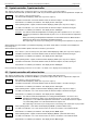
button 1 button 2 button 3
0FFS
S(AL