4 HP GAS ENGINE VERTICAL - OHV Model 96155 Assembly And Operation Instructions IMPORTANT! Your Warranty is voided if: You do not put Engine oil in the Engine’s crankcase prior to its first use. Never run the Engine with low or no Engine oil. Running the Engine with low or no oil will permanently damage the Engine. Due to continuing improvements, actual product may differ slightly from the product described herein. Distributed exclusively by Harbor Freight Tools. 3491 Mission Oaks Blvd.
Specifications Engine Type 4 HP 4-Stroke Gasoline Engine with Vertical Shaft & Recoil Start Air Cooled / Engine Model: 1P60FV-C / Engine Family: 7CLGS.1356V Displacement 119cc Compression Ratio 8:1 Maximum Power Output 4 HP @ 3600 RPM Maximum Torque 3.85 ft-lb @ 2500 RPM Fuel Tank Capacity 0.5 Gal. Engine Oil Capacity 20 Oz.
Work Area 1. Keep your work area clean and well lit. Cluttered and dark areas invite accidents. 2. Do not operate the Engine in explosive atmospheres, such as in the presence of flammable liquids, gases, or dust. Gasoline engines create sparks which may ignite the dust or fumes. 3. Keep bystanders, children, and visitors away while operating a power tool. Distractions can cause you to lose control. Protect others in the work area from debris such as chips and sparks.
Spark Plug Wire before performing any inspection, maintenance, or cleaning procedures. 4. Store idle equipment out of reach of children and other untrained persons. Gasoine engines are dangerous in the hands of untrained users. 5. Maintain tools with care. Keep the Engine clean. Properly maintained engines are less likely to malfunction and are easier to control. Do not use a damaged Engine. Tag damaged engines “Do not use” until repaired. 6.
interference or pacemaker failure. Caution is necessary when near the Engine’s magneto or recoil starter. 6. Never leave the Engine unattended when it is running. Turn off the Engine before leaving the work area. 7. Always use the Engine on a flat, level, dry ground surface. 8. Make sure to keep hands and fingers away from all moving parts of the Engine. 9.
MECHANICAL PRECAUTIONS 1. Prior to performing service, maintenance, or cleaning procedures, always make sure the Engine’s Ignition Switch is in its “OFF” position. Allow the Engine to completely cool. Then, remove the Spark Plug Wire from the Spark Plug. 2. Do not alter or adjust any part of the Engine that is assembled and supplied by the manufacturer or distributor. 3. Always follow and complete scheduled Engine maintenance. CHEMICAL PRECAUTIONS 1.
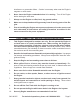
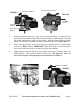
ASSEMBLY INSTRUCTIONS 1. IMPORTANT: If you have any doubts about your ability to perform the following assembly procedures, you should have a qualified service technician perform the assembly for you. 2. Located at the base of the Crankcase Sump (11 - page 13) are four 8mm x 1.25 mounting holes. (See Figure A.) 3. Set the Engine upright on the power equipment unit, and align the four mounting holes of the Engine with four 8mm x 1.25 mounting holes in the power equipment unit.
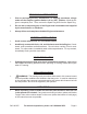
REGULATING MOUNT THROTTLE (1 - page 22) THROTTLE CONTROL CABLE (NOT INCLUDED) FIGURE B OPERATING INSTRUCTIONS 1. Make sure the Engine’s Crankcase is filled with approximately 20 ounces of 10-30W automotive oil. Also, make sure the Engine’s Fuel Tank is filled with approximately 1/2 gallon of unleaded gasoline before attempting to start the Engine. Failure to do so WILL damage the Engine and void the Warranty. 2. To do so, check to make sure the Drain Plug (13 - page 13) is tight.
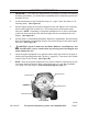
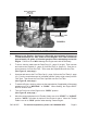
FIGURE C DIPSTICK (2 - PAGE 13) FUEL FILLER CAP (2 - PAGE 18) FIGURE D FUEL TANK (8) (PAGE 18) FILLER (4) (PAGE 13) DRAIN PLUG (13) (PAGE 13) 7. Grasp the Starter Handle (11 - page 21) on the Recoil Starter (12 - page 21) and pull slowly until resistance is felt. Allow the Starter Rope to rewind slowly. Then pull the Starter Handle with a rapid, full arm stroke. Allow the Starter Rope to rewind slowly. If necessary, repeat this process until the Engine starts. (See Figure F.) 8.
INSPECTION, MAINTENANCE, AND CLEANING 1. WARNING! Never perform any services or maintenance on the Engine while it is running. Before performing any inspection, maintenance, and cleaning, turn off the Engine and disconnect the Spark Plug Wire from the Spark Plug to prevent accidental starting. Then, allow the Engine to completely cool. 2. Before each use, inspect the general condition of the Engine.
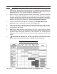
TROUBLESHOOTING Problem Engine will not start. Possible Cause 1. Low on fuel or oil. Possible Solution 1. Add fuel or oil. 2. Ignition switch is in “OFF” position. 2. Turn ignition switch to “ON” position. 3. Faulty spark plug. 3. Clean or replace spark plug. 4. Choke in wrong position. 4. Properly adjust choke. 5. Fuel lever in “CLOSED” position. 5. Turn fuel lever to “OPEN” position. 6. Engine under load during start-up. 6. Remove load from Engine. 7. Spark plug wire loose. 7.
PARTS LIST/DIAGRAM - CRANKCASE Part 1 Description Crankcase Q’ty Part 1 9 Oil Seal (6x11x4) Description Q’ty 1 2 Valve Piece 1 10 Split Pin 1 3 Gauze 1 11 Set Pin (8x14) 2 4 Crankshaft Upper Oil Seal (22x35x6) 1 12 Bearing (62/22 P5) 1 5 Filter Cover 1 13 Oil Bypass 1 6 Gasket 1 14 Bolt (M6x28) 7 7 Washer 1 15 Bolt (M6x14) 2 8 Regulating Sway Bar 1 16 Air Duct 1 IMPORTANT When ordering parts from the above Parts List, make sure to specify the following: a.
PARTS LIST/DIAGRAM - CRANKCASE SUMP Part 1 Description Crankcase Gasket Q’ty Part 1 11 Description Sump, Crankcase Q’ty 1 2 Dipstick 1 12 Washer 1 3 Seal 2 13 Drain Plug 1 4 Filler 1 14 Oil Seal, Crankshaft (25x38x7) 1 5 Sliding Sleeve 1 15 Bolt (M6x32) 1 6 Drive Gear, Regulator 1 16 Washer, Drive Gear 1 7 Washer 1 17 Seal (II) 1 8 Regulating Shaft 1 18 Dipstick with Seal 1 9 Bolt (M6x12) 1 10 Clamp, Regulating Shaft 1 IMPORTANT When ordering parts fr
PARTS LIST/DIAGRAM - CYLINDER HEAD/CYLINDER HEAD COVER Part Description Q’ty Part Description Q’ty 1 Set Pin (10x16) 2 7 Exhaust Valve Guide 1 2 Cylinder Head Gasket 1 8 Circlip 1 3 Stud 4 9 Bolt 4 4 Spark Plug (F6RTCU) 1 10 Gasket, Cylinder Head Cover 1 5 Cylinder Head 1 11 Cylinder Head Cover 1 6 Intake Valve Guide 1 12 Bolt (M6x14) 4 IMPORTANT When ordering parts from the above Parts List, make sure to specify the following: a.
PARTS LIST/DIAGRAM - CRANKSHAFT, PISTON, CONNECTING ROD Part 1 Description Piston Ring (I) Q’ty Part 1 9 Bolt Description Q’ty 2 2 Piston Ring (II) 1 10 Crankshaft 1 3 Scraper Ring Set 1 11 Timing Drive Gear 1 4 Piston Pin Circlip 2 12 Woodruff Key 1 5 Piston Pin 1 13 Crankshaft Kit 1 6 Piston 1 14 Connecting Rod Kit 1 7 Connecting Rod Shank 1 15 Piston Ring Set Kit 1 8 Connecting Rod Cap 1 16 Adjusting Washer 1 IMPORTANT When ordering parts from the above
PARTS LIST/DIAGRAM - CAMSHAFT, VALVE ROCKER Part Description Q’ty Part Description Q’ty 1 Lock Nut 2 10 Valve Spring 2 2 Sleeve 2 11 Spring Seat 2 3 Valve Rocker 2 12 Exhaust Valve 1 4 Adjusting Bolt for Valve Gap 1 13 Pin 1 5 Pusher Guide 2 14 Sleeve, Spring 1 6 Push Rods 2 15 Spring 1 7 Valve Tappets 2 16 Flying Block 1 8 Camshaft 1 17 Camshaft Assy. 1 9 Intake Valve 1 18 Valve Rocker Assy.
PARTS LIST/DIAGRAM - CARBURETOR Part Description Q’ty Part Description Q’ty 1 Carburetor 1 11 Float 1 2 Air Cleaner Gasket 1 12 Float Needle Valve 1 3 Carburetor Gasket 1 13 Main Jet 1 4 Heat Insulator 1 14 Main Jet Pipe 1 5 Inlet Gasket 1 15 Mixture Adjustment Screw 1 6 Float Chamber Drain Screw 1 16 Idle Adjustment Screw 1 7 Washer 2 17 Carburetor Mixture Chamber Body 1 8 Screw 1 18 Choke 1 19 Nut (M6) 2 9 Float Chamber 1 10 Float Chamber Gasket
PARTS LIST/DIAGRAM - FUEL TANK Part Q’ty Part 1 Fuel Filler Cap Assy. Description 1 8 Fuel Tank Description Q’ty 1 2 Fuel Filler Cap 1 9 Fuel Tank Cushion 2 3 Foam 1 10 Washer (10.5x30x1) 1 4 Packing Ring 1 11 Stud 1 5 Pipe Clamp (12.8) 1 12 Bolt (M6x12) 2 6 Pipe Clamp (10.8) 3 13 Bracket 1 7 Outlet Pipe (I) 2 IMPORTANT When ordering parts from the above Parts List, make sure to specify the following: a.
PARTS LIST/DIAGRAM - AIR CLEANER Part Description Q’ty Part Description Q’ty 1 Air Cleaner Bolt (M5x50) 1 5 Gasket 1 2 Air Cleaner Bolt (M5x57) 1 6 Air Cleaner Housing 1 7 Nut (M6) 2 3 Air Cleaner Cover 1 4 Filter Element 1 IMPORTANT When ordering parts from the above Parts List, make sure to specify the following: a. The PART NUMBER listed to the left of the part description. b. The NAME OF THE PARTS LIST from which you are ordering (located at the top of this page).
PARTS LIST/DIAGRAM - MUFFLER Part Description Q’ty Part Description Q’ty 1 Exhaust Gasket 1 3 Muffler Hood 1 2 Muffler 1 4 Fixing Nut 2 IMPORTANT When ordering parts from the above Parts List, make sure to specify the following: a. The PART NUMBER listed to the left of the part description. b. The NAME OF THE PARTS LIST from which you are ordering (located at the top of this page). SKU 96155 For technical questions, please call 1-800-444-3353.
PARTS LIST/DIAGRAM - RECOIL STARTER Part Description Q’ty Part Description Q’ty 1 Starter Hood 1 7 Ratchet 2 2 Bolt (M6) 4 8 Spring Lid 1 3 Fan Hood 1 9 Rolls Pin 1 4 Coil Leaf Spring 1 10 Rope 1 5 Cord Spring 1 11 Handle 1 6 Ratchet Spring 2 12 Recoil Starter Assembly 1 IMPORTANT When ordering parts from the above Parts List, make sure to specify the following: a. The PART NUMBER listed to the left of the part description. b.
PARTS LIST/DIAGRAM - REGULATING CONTROL SYSTEM Part Description Q’ty Part Description Q’ty 1 Regulating Mount with Throttle 1 6 Regulating Arm Assy. 1 2 Choke Link 1 7 Nut (M6) 1 3 Pulling Rod 1 8 Regulating Arm Spring 1 4 Back Spring 1 9 Bolt (M6x12) 2 5 Lock Bolt 1 IMPORTANT When ordering parts from the above Parts List, make sure to specify the following: a. The PART NUMBER listed to the left of the part description. b.
PARTS LIST/DIAGRAM - FLYWHEEL Part Description Q’ty Part Description Q’ty 1 Nut 1 3 Flywheel Fan 1 2 Starting Flange 1 4 Flywheel 1 IMPORTANT When ordering parts from the above Parts List, make sure to specify the following: a. The PART NUMBER listed to the left of the part description. b. The NAME OF THE PARTS LIST from which you are ordering (located at the top of this page). SKU 96155 For technical questions, please call 1-800-444-3353.
PARTS LIST/DIAGRAM - IGNITION COIL Part Q’ty Part 1 Screw (M6x32) Description 2 4 Ignition Coil Description Q’ty 1 2 Sleeve 2 5 Spark Plug Cap 1 3 Engine Stop Cable 1 6 Ignition Coil Assy. 1 IMPORTANT When ordering parts from the above Parts List, make sure to specify the following: a. The PART NUMBER listed to the left of the part description. b. The NAME OF THE PARTS LIST from which you are ordering (located at the top of this page).
PARTS LIST/DIAGRAM - ARRESTING GEAR Part Q’ty Part 1 Tension Spring Description 1 8 Brake Anchor Pin Description Q’ty 1 2 Brake Arm 1 9 Bolt (M3) 1 3 Brake Arm Bolt 1 10 Clapboard 1 4 Washer (8.5x16x1) 2 11 Bolt (M4x12) 2 5 Bolt (M8) 1 12 Flameout Reed 1 6 Friction Plate 1 13 Bolt (M3) 2 7 Bolt (M4) 2 14 Bolt (M6x28) 1 IMPORTANT When ordering parts from the above Parts List, make sure to specify the following: a.
EMISSION CONTROL SYSTEM WARRANTY United States Emission Control Defects Warranty Statement The United States Environmental Protection Agency (herein EPA), and Harbor Freight Tools® (herein HFT) are pleased to explain the emission control system warranty on your 1995 and later Small Off-Road Engine (herein engine). Within the United States, new off-road, spark-ignition engines certified for model year 1997 and later, must meet similar standards set forth by the EPA.
EMISSION CONTROL SYSTEM WARRANTY – (CONT.) Harbor Freight Tools Emission Control Defects Warranty Provisions 5. Service and Maintenance Component parts which are not scheduled for replacement as required maintenance or are scheduled only for regular inspection to the effect of “repair or replace as necessary” are warranted for the warranty period.
LIMITED 90 DAY WARRANTY Harbor Freight Tools Co. makes every effort to assure that its products meet high quality and durability standards, and warrants to the original purchaser that this product is free from defects in materials and workmanship for the period of 90 days from the date of purchase.