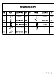
COMPONENTS PART FIGURE DESCRIPTION GTY | PART FIGURE DESCRIPTION atty A <> TOP PANEL 1PC F [ BACK PANEL PCs B LEFT SIDE PANEL | 1PC 8 SN PLASTIC BAR 1PC c RIGHT SIDE PANEL| 1PC H J LEFT DOOR 1PC D << ADJUSTABLE SHELF| PCs ] RIGHT DOOR 1PC E < BOTTOM PANEL | 1PC
HARDWARE & TOOLS PART FIGURE DESCRIPTION | GTY | PART FIGURE DESCRIPTION | QTY 1 @ CAM LOCK | PCS | 8 gg SCREW PCS #15412 $3412 D=7 2 CAM BOLT | PCS | 10 SCREW PCS a on 3 WOODEN DOWEL | PCS | 11 ANCHOR 1PG SCREW specs | 12 q FIX BELT 1c PITH 5 yy, BOLT apes | 13 WASHER PCS 6 ~~ HANDLE 20s | 14 CO CAM COVER | PCS 7
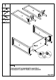
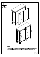
STEP 1: 1. Screw cam bolts (2) and insert dowels (3) in panels Attach panel E to panels B & C and secure with cam locks (1).
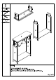
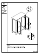
STEP 3: 1. Attach panels F to the back of the cabinet and secure with screws (8) as shown. 2. Insert plastic bar G as shown and finish securing panels F with screws (8).