
Slave to Rhythm Primer - PLL and Clock Basics

PLL and clock basics
External clocking improves the sound of gear.
Sometimes. Sometimes nothing happens,
and in some cases the result is downright
disappointing. What are the factors involved?
This tech note discusses.
Clocks make digital gear tick. Literally: clocks
tell digital devices when to perform the next
step. However, there are only two places where
the stability of that clock affects sound: the
A/D converter chip and the D/A converter
chip. Only there does the clock get to mix with
real life, analog signals because at the moment
of conversion clock timing errors convert into
amplitude errors. To understand what external
clocking does to this clock that the converters
see, we need to understand the path followed
by the external clock signal.
Converter chips need a high frequency clock
signal, usually something around 22MHz. It
is always made by a local oscillator (anything
from a simple RC oscillator in a receiver chip
to a crystal oscillator) regardless of whether
the unit is operating in master or slave mode.
This local oscillator is indispensible: external
sync signals may be AES/EBU, a sample rate
frequency “word clock” or even a video signal,
neither of which are of any direct use to the
AD/DA. Instead, the local oscillator is sped up
or slowed down to make it run in step with
(“locked to”) the sync signal. A system that
uses a local oscillator “pulled” in sync with an
external signal is called a Phase Locked Loop
(PLL). A “phase detector” compares the local
clock with the external sync signal and puts
out a signal when the local oscillator runs too
fast or too slow.
Now, the PLL will track the external sync
closely, but not too closely. Unwanted
fluctuations (jitter) of the external sync signal
are to be ignored but if the local oscillator
drifts off it should be pulled back into step. So
how does the PLL tell the difference? It can’t.
It sees only the difference between the two
clocks.
All it can do is ignore short term differences
(high-frequency jitter), whilst tracking slower
fluctuations (low-frequency jitter). After all, a
slow change could be due to drifting of either
the external sync signal or the local oscillator.
Either way, the PLL must get the local
oscillator to follow the sync at long last, lest
lock be lost.
The cut-off point between “slow” errors and
“fast” errors (known as the “PLL bandwidth”)
is chosen by the designer, based on an
assumption of how stable the local oscillator is
compared to the external sync signal. Above
the cut-off point, the PLL will not reproduce
any errors present in the input, but neither will
it be able to correct errors committed by its
own local oscillator.
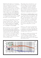
Here’s the transfer of a basic PLL, designed to
have a cut-off frequency of 4kHz.