Please read this manual before operating the unit!
TPInLB
Table of Contents Introduction 4 Important Safety Instructions 5 1. Installing 7 2. Signal Connections 8 3. Operation 8 4. Setting up the Studio 12 5. Pro Tools 16 6. Jitter and PLL’s explained 18 7. Specifications 23 8.
Introduction Thank you for choosing the Grimm Audio CC1 Central Clock distributor for your production environment. This product features a rich set of distributor functions, based upon an ultra low jitter clock oscillator. It embodies our company philosophy of providing the most transparent signal chain possible, enabling you to achieve the best possible results sonically and artistically. Large parts of the CC1 circuitry, like the oscillator and its power supplies, use a discrete design.
Important Safety Instructions Grimm Audio gaat er van uit dat u deze Engelstalige tekst volledig begrijpt. Als u hier moeite mee heeft dient u contact op te nemen met Grimm Audio. Op verzoek sturen wij u een vertaling toe. Grimm Audio nimmt an, dass Sie diesen Englischen Text völlig verstehen. Wenn notwendig, nehmen Sie bitte Kontakt auf mit Grimm Audio. Auf Wünsch wird Ihnen eine Übersetzung zugeschickt. Grimm Audio suppose que le lecteur comprend parfaitement le texte en Anglais ci-dessous.
10. Do not use this apparatus near water. 11. Do not use this apparatus outside. 12. Do not expose the apparatus to dripping or splashing. Do not place objects filled with liquids (flower vases, drink cans, coffee cups, etc) on the apparatus. 13. Clean only with a dry, soft, non-fluffy cloth. Do not spray any liquid cleaner onto the cabinet, as this may lead to dangerous shocks. Do not spray any liquid cleaner onto the faceplate, as this may damage the front panel. 14.
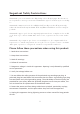
1. Installing Unpacking and Inspection Your CC1 was carefully packed at the factory and the carton it came in was designed to protect it from the trials and tribulations of shipping. Keep the box and all packing materials, so that in the unlikely event that you need to return the CC1 for servicing, you can do so safely. Mounting the CC1 The CC1 can mount in any standard 19” rack. The CC1 does not produce RF fields nor is susceptible to them.
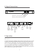
2. Signal Connections Toggles Master 44.
The AES3 output has two functions, depending on the setting of the dip switch marked “aes” on the rear. It determines whether the audio content found at the AES3 input is passed through to the output (“thru”) or not (“mute”). In “mute” mode the AES3 data will be black and run at the rate selected for group 2. In “thru” mode, the AES3 output will obviously run at the same rate as the AES3 input. On loss of input signal, the output will remain at the same sampling rate.
nel status marked “no reference”. Upon loss of lock, the output frequency will be held constant, see case 4. 2. AES3 only. Upon selection of slave mode, the CC1 selects the AES3 input. The “aes” dip switch at the rear selects whether the audio data is transmitted (thru) or not (mute). In thru mode, the AES3 output will obviously run at the same multiple as the AES3 input. In mute mode it will be synchronous to group 2, audio is black and marked “no reference”.
The “lock” LED on the rear indicates the AES3 receiver status: 1. Off: No AES3 signal present. 2. On: AES3 signal present and found to be synchronous with the CC1. 3. Blinking: An AES3 signal is present but it is out of sync with the CC1. Impedance The “impedance” DIP switches on the rear allow each individual output to be set to low-impedance (25 ohms typical) or characteristic (75 ohms) impedance. The switches are factory set to 75 ohms.
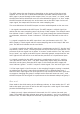
AES and unlock switches The ‘aes’ and ‘unlock’ switches can be set to ‘‘mute’ or ‘thru’. The behavior of the CC1 in these modes is described in Chapters ‘Master mode’ and ‘Slave mode’. Key Lock mode If your CC1 is used in one setting most of the time you can use “Key Lock” mode to prevent clocking errors by accidental pressing of control buttons on the CC1’s front panel. In this mode the CC1 does not respond to the push of any button. “Key Lock” mode is engaged by holding the “44.
Connection The CC1 will usually be located in the machine room. Each device connected to the CC1 is set to “slave to word sync”. The best connection scheme is “star distribution” with each output of the CC1 connected to one device. The sixteen outputs will normally suffice. Daisy chain connections are best avoided, as are T-junction connections.
In consumer use, most equipment features RCA S/PDIF connectors in stead of XLR AES3 connectors. To facilitate Hi-Fi use of the CC1, all our consumer units are shipped with an S/PDIF <-> AES3 conversion cable set. Clock Loop A clock loop is a runaway situation where two devices are slaved to eachother, for instance the CC1 slaved to a recorder which in turn is slaved to the CC1.
sync, but fortunately it is going out of fashion. LTC is probably the least stable time reference around. Enter digital audio. The audio track now needs to be synchronised to the picture. Word sync has a better time resolution than video sync, but still the most common practice is locking the audio clock to the video clock. Even modern digital video production practice tends to lock audio to an analogue video signal.
5. Pro Tools Avid Pro Tools is by far the most common DAW, warranting a special section on how to set up the CC1 in a PT rig. In our experience described method is the set-up that leads to the best sound quality. Any deviation from this method might give you stable sync, but will probably not be sonically optimal.
the whole system will automatically track the project’s sample rate. Disadvantage is that in theory jitter on the CC1’s outputs will be slightly higher. The CC1’s jitter attenuation however is so large we do not expect this to be a problem. • Connect the Loop Sync output of the Sync I/O (which is first unit in the chain) to the word clock input of the CC1. Put CC1 in slave mode. • Connect the outputs of CC1’s group 1 and/or group 2 to the Loop Sync input of each “192” interface.
Setup – Peripherals 1. On the “Synchronisation” tab: select device “Sync HD” and port “any” (the LTC input will be automatically selected) 2. On the “Machine Control” tab: tick “9 pins serial” (Sony P2). Untick “use serial time code for positional reference”. Leaving this option ticked causes the Sync HD to try syncing to video sync instead of word sync. An additional disadvantage of Sony P2 is that it does not sport a “continuous resync” like LTC, signaling time code only together with transport commands.
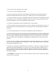
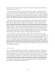
A stable and a jittery clock signal Amplitude We can also look at the problem spectrally. An ideal clock has only a single frequency components (and harmonics). All energy is concentrated on an infinitely narrow frequency band, see the top picture below. When jitter is present, side bands occur. Some spectral energy is located away from the clock. The faster the timing chatters, the further away from the main frequency you’ll find energy.
but as far as signal quality is concerned you’re better off with a stable clock at an inexact frequency. Jitter is not a problem in fully digital processes. As long as it isn’t so large that a processor can’t distinguish the previous bit from the next, all-digital processes are completely indifferent about jitter. The problem occurs when you go from the analogue domain into the digital domain or back. Digital audio presumes uniform sampling.
external sync signal and puts out a signal when the local oscillator runs too fast or too slow. Now, the PLL will track the external sync closely, but not too closely. Unwanted fluctuations (jitter) of the external sync signal are to be ignored but if the local oscillator drifts off it should be pulled back into step. So how does the PLL tell the difference? It can’t. It sees only the difference between the two clocks.
to lock and has a 0.1Hz bandwidth. Typical AES/EBU receiver chips lock within a few samples and have a bandwidth of around 10kHz. If the local clock is very clean, a narrowband PLL is the best choice because all but the lowest-frequency jitter in the external sync is rejected. A converter designed along those lines will sound stellar under all conditions. If the external sync is very clean, a wideband PLL is the best choice because the local oscillator’s own errors will be corrected.
7. Specifications The clock PLL is a hybrid analog / digital design, based on a discrete design ultralow jitter crystal oscillator. In master mode the oscillator is temperature compensated. Local shunt regulators featuring 120 dB power supply rejection and a high impedance supply path, thus all variations in load current are kept local to the circuit: the power buss and ground carry only DC current. Specifications Word Word Word Word clock clock clock clock input impedance 75 Ohm.
Grimm Audio contact information Grimm Audio CV Strijpsestraat 94 5616 GS Eindhoven The Netherlands +31 (0)40-213 1562 Email: info@grimmaudio.com Website: http://www.grimmaudio.
8. Grimm Audio Limited Warranty Grimm Audio CV (“Grimm Audio”) warrants this product to be free of defects in material and workmanship for a period of one (1) year for parts and for a period of one (1) year for labor from the date of original purchase. This warranty is enforcable only by the original retail purchaser and cannot be transferred or assigned.