Crathco® Powdered Beverage Dispensers Service Manual for PIC 1, 2, 3, 4, 5, 6 PSD 1, 2, 3, 4, 5, 6 PIC 23A, PIC33A, PIC43A, PIC5W TABLE OF CONTENTS Warning Labels....................................... 2 Installation.............................................. 4 Start up Procedures................................. 4 How To Dispense Cappuccino.................. 5 Adjustments............................................ 5 Cleaning..................................................
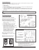
Warning Labels The following warning labels were on your dispenser when it was shipped from the factory. They should remain on your dispenser in good, readable condition at all times. If one of your labels is missing or damaged, order a replacement label immediately. Part #62981 (PIC 5-6) - Located on the upper splash panel on the front of the dispenser WARNING Contents can cause severe burns if handled improperly.
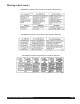
Warning Labels (cont.
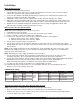
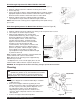
Installation Water Inlet Connection The following is required for water hook-up: 1. A quick disconnect water connection or enough coiled tubing so the machine can be moved for cleaning underneath. (required for NSF approved water hook-up) 2. A 1/4" male flare adapter is provided (packed inside the drain tray) to be attached by the installer to the back of the machine for hook-up to water supply. 3. Installation to a water filter system is required to prevent lime and scale build up in the machine. 4.
Installation (cont.) Start-Up Procedures for Pump Units (PIC 2P & PIC 3P only) (cont.) NOTE: Do not let the end of the hose touch the bottom of the container. Shorten the hose if necessary. If you need a longer hose, remove the back access panel, unclamp existing hose, replace with longer hose and replace clamp. 3. Proceed with fifth step under Start Up for Standard Units.
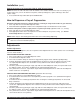
Thermostat Adjustment NOTE: The thermostat range is approximately 160°F to 200°F. The tank temperature is factory set at 180°F, making the beverage temperature slightly lower than 180°F. 1. 2. 3. 4. 5. Unplug machine. Remove the drip tray. Remove the upper splash panel on the front of the machine by removing the four Phillips head screws. Locate the thermostat adjustment dial on the control board(s).
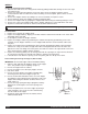
Drink Strength Adjustment for Model PIC3E or PIC33AE when equipped with remote adjust knobs behind drip tray (Refer to Figure C) 1. Dispense a drink to determine if drink is too strong or too weak. 2. Remove drip tray. 3. Using a flat head screwdriver, adjust individual dispense heads by rotating appropriate adjustment knob. Clockwise rotation will result in a stronger drink and counterclockwise rotation will result in a weaker drink. 4.
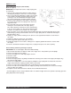
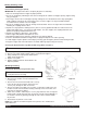
WEEKLY Removing and Cleaning the Chambers 1. Open the door and remove the mixing funnel shroud by pulling forward while turning 1/4 turn to the right. Lift off and remove. 2. Remove the mixing funnel by lifting the neck of the funnel out of the whipper chamber, then tilt counterclockwise. With one hand on the water inlet fitting on the back panel, pull the funnel out of the white ring. 3. Remove the whipper chamber by rotating it 1/8 of a turn clockwise, then pull to remove. 4.
WEEKLY (cont.) Reassembling the Hoppers (PIC 1/2/3/5/6) (Refer to Figure I) IMPORTANT: All components must be completely dry prior to reassembly. 1. Place the drive shaft bearing inside the hopper with the threads going through the hole in the rear of the hopper. 2. Secure the bearing by attaching the palnut to the bearing at the outside rear hopper opening. Tighten using only your fingers. Use one hand inside the hopper to push the bearing outward while turning the palnut clockwise. 3.
Weekly Cleaning (cont.) Reassembling the Hoppers (PIC 4) IMPORTANT: All components must be completely dry prior to reassembly. 1. Place the bearings inside the hopper in proper position. 2. Secure the bearings by attaching the nuts to the bearings at the outside rear hopper opening. Tighten using only your fingers. 3. Insert auger into the lower front hopper opening, making sure the threaded end of the auger spring drive shaft completely inserts into the rear bearing in the rear of the hopper.
PIC Preventative Maintenance Checklist (Every 6 to 12 months) A preventative maintenance visit should be performed every 6 to 12 months, depending on usage. The following procedures should be performed during a preventative maintenance visit. Parts Required: One PM parts kit (PIC1 - Qty1 - 62707, PIC2 - Qty2 - 62707 or Qty1 - 60933, PIC3 - Qty1 - 60933, PIC4 - Qty1 - 60933 and Qty1 - 62707, PIC5 - Qty2 - 60933, PIC6 - Qty2 - 60933).
Service Changing the Lightbulb on Models With a Backlit Merchandiser (PIC 1/2/3/4/5/6) (Refer to Figure M) (Refer to serial tag to verify model number of your machine) Disconnect machine from branch electrical supply before changing WARNING: the lightbulb. NOTE: PIC2/3/4 uses a F8T5 12" 8 watt replacement bulb. PIC5/6 uses a 22W circular bulb. 1. All: Remove the front merchandiser photo and cover by grasping the edges of the merchandiser. 2. PIC1: Lift bulb out of socket vertically.
Draining the Tank (PIC 2/3/4 ) (cont.) 7. Once the tank is empty, securely replace the plug and clamp on the end of the hose. Reposition the drain hose inside the hose clip on the left side wall. 8. Reassemble the front access panel and drain tray. Purging Machine of All Water for Shipment in Cold Areas WARNING: This procedure should be performed by a qualified service technician. 1. Turn the power switch to the "OFF" position. 2. Drain the water tank (refer to instructions on page 12).
Removal of Whipper Motor(s): 1. 2. 3. 4. 5. 6. 7. Disconnect power. Remove front and side access panels. Remove chamber. Remove whipper base. (Figure Q) Remove motor nuts and pull motor out of slot. (Figure R, S) Disconnect wire connection. (Figure T) Replace motor as needed. Figure Q Figure R Figure S Figure T Replacing Dump Valves, Dump Valve O-rings, and/or Tank Grommets 1.
Replacing Water Tank on Machines with Serial # 339304 and Lower: (cont.) 4. Disconnect dump valve wiring and tubing in left access opening and remove valves. 5. Disconnect tank fill tubing from inlet valve in rear of unit. 6. Remove screws holding water tank and mounting bracket. Remove tank, bracket and old tubing (NOTE: Do not discard dump valve tubing). 7. Remove heating element, thermal probe, water probe, vent fittings, and valve retaining clip from old tank.
Removal of Water Tank on Machines with Serial # 339305UK and Higher: 1. 2. 3. 4. 5. 6. 7. 8. Disconnect power. Drain tank. (see page 12) Remove machine lid, rear access panel and dump valve access panel. (Figure BB) Disconnect wires from tank lid components and dump valves. (Figure CC) Disconnect hoses from dump valves. Remove mounting screws from rear of tank. (Figure DD) Disconnect drain hose from bottom of tank. (Figure EE) Lift out tank and replace as needed.
Removal of Thermistor 1. 2. 3. 4. 5. Disconnect power. Remove machine lid. (Figure JJ) Disconnect thermistor wires. (Figure KK) Lift out thermistor and replace as needed. (Figure LL) To replace with thermistor, add food grade lubricant.
Removal of Auger Motor(s) 1. 2. 3. 4. Disconnect power. Remove front and side access panels. Remove hoppers. Remove three screws and lock washers. (Figure NN) 5. Pull motor out of slot. (Figure OO) 6. Disconnect wire connection. 7. Replace motor as needed. Figure NN Figure OO Removal of Blower Motor 1. 2. 3. 4. 5. 6. 7. 8. 9. Disconnect power. Drain tank. (see page 12) Remove rear access panel. Disconnect black hose from fan. Disconnect hose from inlet valve if needed. Remove two screws from side.
Crathco® Powdered Beverage Dispensers Page 19
Troubleshooting Guide Only a qualified service technician should perform Electrical and mechanical adjustments or repairs. Always disconnect power before attempting any maintenance procedures.
Troubleshooting Guide (cont.) Only a qualified service technician should perform Electrical and mechanical adjustments or repairs. Always disconnect power before attempting any maintenance procedures. Diagnostics for all PIC2, PIC3, PIC4, PIC5, and PIC6’s: WTR FAIL = Light flashes when watchdog timer disables machine after 300 seconds of continuous inlet valve operation. THERM FAIL = Light flashes when thermistor fails or thermistor is disconnected. WTR HEATER = Light flashes when heater is on.
PIC 1 Chassis Parts (units with serial numbers beginning with “L”) 63493 Page 22 63493 63493 Crathco® Powdered Beverage Dispensers
PIC 1 Hopper Bracket (units with serial numbers beginning with “L”) Crathco® Powdered Beverage Dispensers Page 23
PIC 1 Door Assembly (units with serial numbers beginning with “L”) Page 24 Crathco® Powdered Beverage Dispensers
PIC 1 Tank Assembly (units with serial numbers beginning with “L” or “T”) ( * ) ( *** ) (*) = 71610 REPAIR KIT FOR DUMP VALVE (***) = 61365 DUMP VALVE O-RING Crathco® Powdered Beverage Dispensers Page 25
PIC 1 Chassis Parts (units with serial numbers beginning with “T”) 63493 Page 26 63493 63493 Crathco® Powdered Beverage Dispensers
PIC 1 Hopper Bracket (units with serial numbers beginning with “T”) $2!7).'Ĥ ' %80,/$%$Ĥ6)%7Ĥ (/4 $ #/, 0!24Ĥ.5-"%23 6/,4 % 6/,4 * 6/,4 1 6/,4Ĥ * ./4% ./ 6/,4 . ! . ! . ! . ! . ! . ! . ! . ! . ! $%3#2)04)/. 37)4#( Ĥ30$4Ĥ4/'',% ,!"%, Ĥ(/4Ĥ/2Ĥ#/,$ (!2.%33 Ĥ!-" Ĥ4%-0 /04)/.!,Ĥ!-")%.
PIC 1 Door Assembly (units with serial numbers beginning with “T”) 63097 Page 28 63097 63097 Crathco® Powdered Beverage Dispensers
PIC 2/3 Chassis Parts Crathco® Powdered Beverage Dispensers Page 29
PIC 2/3 Hopper Bracket Page 30 Crathco® Powdered Beverage Dispensers
PIC 2/3 Tank Assembly Crathco® Powdered Beverage Dispensers Page 31
PIC 2/3 Door Assembly Page 32 Crathco® Powdered Beverage Dispensers
PIC 4 Chassis Parts 63493 Crathco® Powdered Beverage Dispensers Page 33
PIC 4 Control Bracket Assembly Lid Page 34 Base Crathco® Powdered Beverage Dispensers
PIC43A Control Bracket Assembly Crathco® Powdered Beverage Dispensers Page 35
PIC 4 Hopper Bracket Funnel Whipper Shroud Page 36 Crathco® Powdered Beverage Dispensers
PIC 4 Hopper 62639 Hopper Assy 5.5# PIC4 (use for sugar-based powders) 62640 Hopper Assy 11# PIC4 (use for sugar-based powders) PE 32 63078 Hopper Assy 5.
PIC 4 Tank Assembly ,7(0 12 3$57 12 '(6&5,37,21 &RYHU 3,& :HOGHG 7DQN /LG 3UREH 7KHUPLVWRU (OHPHQW 187 137 %5$66 (QWHU 7LWOH 352%( 3,& 7 67$7 +, 7(03 /,0,7 *5200(7 6,/,&21( :+7 7XELQJ ,'[ :/ 6LOLFRQH &ODPS +RVH ,' +H\FR (OHPHQW 9 : (OHPHQW 9 : 187 66 :,7+ 1
PIC 4 Door Assembly Crathco® Powdered Beverage Dispensers Page 39
PIC 4 Final Assembly Page 40 Crathco® Powdered Beverage Dispensers
PIC 5 Casing Assembly (Part # 62813) 63493 PIC 5 Base Assembly (Part # 62819) Crathco® Powdered Beverage Dispensers Page 41
PIC 5 Control Bracket Assembly (Part # 62974) 2 PIC 5 Lid Assembly (Part # 62810) 1 11 4 6 4 1 3 5 3 12 5 3 2 ITEM NO. PART NO. DESCRIPTION 1 62849 Bracket, Control Mtg PIC5 No Display 2 61338 Terminal Board 3 61800 Controller,Pic 3 Portion 4 61131 Relay,12 vdc Coil 5 61481 Transformer,40VA 24/12S 6 61266 STANDOFF, RVRS EDGEMOUNT 7 10073 Label, Ground Symbol 8 60394 Bushing,Snap-7/8"OD x 3/4" ITEM NO. PART NO.
PIC 5 Hopper Bracket Assembly (Part # 62850) 25 23 62850 - Hopper Brkt Asy PIC5 33 26 8 40 7 41 37 39 6 36 1 10 15 4 24 34 9 11 5 38 14 27 35 2 12 20 3 13 31 30 29 28 32 21 22 3 16 17 18 16 19 ITEM NO. PART NO. DESCRIPTION ITEM NO. PART NO. DESCRIPTION 1 62851 Bracket, Hopper PIC5 23 60381 Rivnut, 6-32 ALS4-632-80 2 61461 Button, Restrictor 24 61250 Washer, #8 Split Lock 3 61847 Switch,Toggle-Spst 25 61159-19-5 Seal, Closed Cell Foam 16.
Page 44 Crathco® Powdered Beverage Dispensers
PIC 5 Final Assembly 6 11 PIC5 - FINAL ASSEMBLY 28 40 1 28 9 25 22 5 14 24 17 7 20 18 13 30 23 3 21 34 10 19 40 35 28 2 16 31 15 16 8 4 39 16 12 ITEM NO. PART NO. DESCRIPTION ITEM NO. PART NO.
PIC 6 Casing Assembly (Part # 62872) 63493 PIC 6 Base Assembly (Part # 62876) Page 46 PIC 6 Lid Assembly (Part # 62874) Crathco® Powdered Beverage Dispensers
PIC 5/6 Control Bracket Assembly (Part # 62848) 62848 - Control Bracket Assy PIC6 ITEM NO. 11 2 6 7 4 4 PART NO.
PIC 6 Hopper Bracket Assembly (Part # 62863) 26 1 31 30 7 29 35 34 36 6 37 8 9 4 32 5 10 13 25 11 15 3 28 14 2 22 33 20 21 3 19 18 Page 48 ITEM NO. PART NO. 1 62864 2 3 DESCRIPTION 17 62863, Hopper Brkt Assy PIC6 PIC6 Manual-3.drw ITEM NO. PART NO. Bracket, Hopper PIC6 24 61250 DESCRIPTION 61461 Button, Restrictor 25 62891 Harness, Hopper Brkt PIC5/6 61847 Switch,Toggle-Spst 26 61159-23.5 Seal, Closed Cell Foam 16.
PIC 6 Final Assembly 62917 62914 62981 62922 Drain Grid PIC6 62992 Crathco® Powdered Beverage Dispensers Page 49
PIC 1 120V and 120/240V “Q” Model Wiring Page 50 Crathco® Powdered Beverage Dispensers
PIC 1 230V “E” Model Wiring Crathco® Powdered Beverage Dispensers Page 51
PIC1KE or PIC1KAE, 230V “E” Model Wiring Page 52 Crathco® Powdered Beverage Dispensers
PIC1K or PIC1KA 120 & 120/240 “Q” Model Wiring Crathco® Powdered Beverage Dispensers Page 53
PIC1KAEW or PIC1KEW Wiring Page 54 Crathco® Powdered Beverage Dispensers
CAP1AE or CAP1E 230V “E” Model Wiring Crathco® Powdered Beverage Dispensers Page 55
PIC 2/3 120 & 120/240V “Q” Model Wiring Page 56 Crathco® Powdered Beverage Dispensers
Crathco® Powdered Beverage Dispensers Page 57
PIC33AE 230V “CE” Model Wiring with 3-Portion Touch Pads Page 58 Crathco® Powdered Beverage Dispensers
PIC 2/3 100 & 200V “J” Model Wiring Crathco® Powdered Beverage Dispensers Page 59
PIC23A, PIC33A 100 & 200V “J” Model Wiring with 3-Portion Touch Pads Page 60 Crathco® Powdered Beverage Dispensers
PIC3E or PIC3AE, 230/240VAC 50/60Hz Model Wiring with Remote Portion Control Crathco® Powdered Beverage Dispensers Page 61
PIC 4 Wiring Page 62 Crathco® Powdered Beverage Dispensers
PIC43A 120V & PIC43AQ 120/240V Wiring Crathco® Powdered Beverage Dispensers Page 63
PIC43AZ and PIC43AWZ Model Wiring with 3-Portion Touchpad Page 64 Crathco® Powdered Beverage Dispensers
PIC4Z, PIC4AZ, PIC4WZ, PIC4AWZ 240V Model Wiring Crathco® Powdered Beverage Dispensers Page 65
PIC 5/6 Wiring Page 66 Crathco® Powdered Beverage Dispensers
Crathco® Powdered Beverage Dispensers Page 67
Grindmaster® Coffee Grinders and Brewers • PrecisionBrew™ Brewing Systems • Espressimo® Espresso Machines Crathco® Hot Beverage Dispensers • Crathco® Cold and Frozen Beverage Dispensers • AMW Coffee and Tea Systems Tel (502) 425-4776 • Fax (502) 425-4664 • 1-800-695-4500 (USA & Canada only) P.O. Box 35020 • Louisville, KY 40232 • USA www.grindmaster.com • email: info@grindmaster.