Shuttle® Brewer & Airpot/Shuttle® Brewers Operation and Instruction Manual For Models APB-330V2, APB-430V2, APBVSA-330V2, APBVSA-430V2, APBIC-330V2, APBIC-430V2, APB-330V2E230, APB-430V2E230, APBVSA-330V2E230, APBVSA-430V2E230, APBIC-330V2E230, PBIC-430V2E230 Table of Contents Warning Labels . . . . . . . . . . . . . . . . . . . . . . . . . . 3 Installation and Start-up . . . . . . . . . . . . . . . . . . . 4 Operation . . . . . . . . . . . . . . . . . . . . . . . . . . . . . . 6 Adjustments . . . . . . .
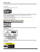
Warning Labels The following warning labels were on your dispenser when it was shipped from the factory. They should remain on your dispenser in good, readable condition at all times. If one of your labels is missing or damaged, order a replacement label immediately. Part # A546-445 Located on front splash panel and lid of machine. Located on APB-330V2, APB-330V2E230, APB-430V2, and APB-430V2E230 lower front decal. Order part # A546-434 for APB-330V2. Order part # A546-435 for APB-430V2.
Installation WARNING ELECTRIC SHOCK HAZARD! Installation of this appliance should be performed by qualified service personnel only. Improper installation could result in electrocution. Set-Up/Position 1) Remove the brewer from the packing material and attach its legs. 2) Position the brewer on a strong, stable table or counter. Check the level front to back and side to side. Adjust the legs to the correct level.
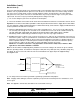
Installation (cont.) Electric Hook-up The brewer is designed to operate at the specified voltage on the nameplate with a tolerance of ± 10% for voltage deviation. It is very important that the power line to the brewer be checked to make sure that the voltage is within 10% of the brewer’s rated voltage. Failure to provide adequate voltage, as defined above, will cause problems with your brewer. If the power is too low, the solenoid valves may or may not work or longer recovery time will be experienced.
Installation (cont.) Start-up 1) Flip power supply to machine “ON” at the branch supply disconnect and allow the water tank to fill. The machine will make a subtle hissing sound while filling. Attention: A watchdog circuit monitors the fill valve “ON” time. If the “ON” time exceeds 6 minutes continuously, the brewer will display message “ER1” and cease operation. Normal initial fill time on some models exceeds 6 minutes.
Adjustments All adjustments to machine are accessible through the front display(s). Refer to specifics below and the Programming Routine section. All values are preset at the factory and may vary brewer to brewer. Temperature Adjustment Tank temperature can be adjusted from 170°F – 205°F (77°C – 96°C) through the front display. See Programming Routine section for procedure. This brewer can be set for maximum water temperature of 205°F (96°C). The boiling point of water is lower as altitude increases.
Adjustments (cont.) Brew Volume “br” Brew time can be set for each size visually. See Setting Brew Volume Procedure below. Brew time can also be adjusted through the display. See Programming Routine section. Setting Brew Volume Visually 1. Remove brew basket and place container under brew head. 2. Press and hold desired brew button for 5 seconds. Display will read “Pro”. 3. Within 20 seconds, press and release desired brew button. Water will dispense from spray head and time will count-up in display. 4.
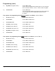
Programming (cont.) To program the following items, press the Large, Right side portion button. (refer to Table 1) 1) Temperature Scale: Choose °F or °C 2) Set Water Tank Temperature: Choose between 170°F - 205°F 3) EnErGy mOdE: Choose YES or NO 4) Ltn (Low Temp No Brew): Choose YES or NO • If YES, the brewer will only allow a brew to begin if the water tank temperature is within 5°F of set point. • If NO, the brewer will brew at any temperature.
Programming (cont.) 13) By-PASS (Set bypass volume): Choose OFF to 25% Set the amount of bypass desired during brew. If none is desired then set to OFF, otherwise, set the % of brew volume to bypass. 14) CoPY-to-LEFt: Choose YES or no If the same program parameters are desired on same portion size on the left side, then choose YES and the parameters will be copied.
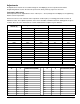
Programming Sequence for Large Left Portion Table 1 OG G O S S PRESS-AND-HOLD UP & DOWN ARROWS FOR 5 SECONDS. DISPLAY WILL READ AS FOLLOWS: DISPLAY READING TEMP SCALE OR TANK TEMP (170-202F) OR ADJUST ADVANCE ENERGY MODE ENERGY MODE OR LOW-TEMP/NO-BREW LOW-TEMP/ NO-BREW OR DRIP TIME DRIP TIME PERCENT OF BREW TO BYPASS RATIO OR BREW TIME BREW TIME (.01 TO 6.00) PRE INFUSION PRE INFUSION TIME (OFF TO 2.
Programming Sequence for Large Left Portion (cont.) Table 1 (cont.) DISPLAY READING ADJUST ADVANCE PRE INFUSION PRE INFUSION OFF TIME (.05 TO 2.00) TO PULSE BREW # OF PULSES (OFF, 1 - 10) TO PULSE ON PULSE ON TIME (0:05-2:00) PULSE OFF PULSE OFF TIME (0:05-2:00) BY-PASS OFF TO .
Programming Sequence for Medium Portions Table 2 OG G O S S PRESS-AND-HOLD UP & DOWN ARROWS FOR 5 SECONDS. DISPLAY WILL READ AS FOLLOWS: DISPLAY READING ADJUST ADVANCE BREW TIME BREW TIME (.01 TO 6.00) PRE INFUSION PRE INFUSION TIME (OFF TO 2.00) TO PRE INFUSION PRE INFUSION OFF TIME (.05 TO 2.
Programming Sequence for Medium Portions (cont.) Table 2 (cont.) PRESS-AND-HOLD UP & DOWN ARROWS FOR 5 SECONDS.
Programming Sequence for Small Portions Table 3 OG G O S S PRESS-AND-HOLD UP & DOWN ARROWS FOR 5 SECONDS. DISPLAY WILL READ AS FOLLOWS: DISPLAY READING ADJUST ADVANCE BREW TIME BREW TIME (.01 TO 6.00) PRE INFUSION PRE INFUSION TIME (OFF TO 2.00) TO PRE INFUSION PRE INFUSION OFF TIME (.05 TO 2.
Cleaning WARNING Burn Hazard! Hot liquids and surfaces are present in this equipment. To avoid burns use caution when cleaning. Rinse hot parts with cold water before cleaning. Use gloves or a heavy cloth when removing hot parts from brewer. After Each Brew: 1) Dispose of grounds and rinse brew basket. 2) Rinse Shuttle or airpot containers before reuse. Every Day: 1) Wash brew basket with warm soapy water. The wire basket is removable to aid cleaning.
Service The rest of this manual contains information to aid the service person who is working on this equipment. This page has information on performing common service tasks. Following this is the Troubleshooting section which can help diagnose problems which are divided into three basic systems: filling, heating, and brewing. Next is an illustrated parts breakdown which will help in the selection of repair parts.
Special Control Functions User Lockout User Lockout is achieved via the position of the LOCK jumper on the board header. Locate the header on the board (shown below) and place the jumper in the desired position. In the Locked position all menus in this document are locked out, and the unit will only allow brewing functions. There are two versions of the header, 10 pin and 2 pin. Both configurations are shown below.
Factory/Field Test Menu (cont.) Step Function Operation Description 1 LED Test All LEDs ON Verify that all LEDs turn on. 2 Firmware Version Display firmware version Shows the software version of the control.
Troubleshooting The following pages are provided to help determine the cause of problems with operation of the brewers and to indicate the appropriate solution for the problems. For each problem, the possible causes should be checked in the order shown until the exact nature of the problem is determined. The following procedures must be performed by a qualified service technician. Disconnect power to machine before servicing.
Troubleshooting (cont.) Filling Problems Problem Tank does not refill Possible Causes Service Check Remedy • No electrical power to equipment • Check for proper • Establish electrical power voltage at terminal to unit. block. Check circuit breaker on supply circuit. • No water supplied to equipment • Disconnect water supply line and ensure that water is provided to unit. Check to see that any and all valves in water line are open.
Troubleshooting (cont.) Filling Problems Problem Tank does not refill Possible Causes • Fill valve or control board is faulty Service Check Remedy • Check to ensure proper • If 6 pin connector is securely connection between attached to control board and 6 pin connector and con- all connections are secure trol board. Check and there is 24 Vac across for proper connections fill valve terminals, replace at fill valve terminals. fill valve. Drain 1 gal. (3.8L) of water from hot water faucet.
Troubleshooting (cont.) Heating Problems Problem Tank does not heat Possible Causes Service Check Remedy • Low (long) electrode coated with lime or faulty. • Disconnect electrode • Remove electrode assembly wire at quick connect and clean the probes. If (purple wire). Connect a problem is not corrected, wire from the quick conreplace electrode assembly. nect to the cabinet body. If heating begins, this is the error cause. • Connection from control board to tank body faulty.
Troubleshooting (cont.) Heating Problems Problem Tank does not heat Possible Causes Service Check Remedy • Contactor faulty. • Ensure that coil on • If the contactor coil is contactor is energized energized and there is an by ensuring that there open circuit across any of is proper voltage the contactor poles, replace between the brown and contactor. white wires attached to the relay. Check each side of the contactor (Line and Load) at each pole for continuity. • Heater faulty.
Troubleshooting (cont.) Brewing Problems Problem Brew volume too large or too small Brew volume erratic Possible Causes Service Check Remedy • Sprayhead clogged. • Visually check for clogging of holes in brewhead. • Clean all holes. • Brew valves clogged with lime deposits. • Visually inspect brew valve at hose connections. • Clean lime from valve. Seat, cup or entire valve may need replacement. • Water supply pressure or flow rate not adequate.
Troubleshooting (cont.) Brewing Problems Problem Possible Causes Service Check Remedy Brew cycle will not start • Controller faulty. • Check to see that the • If there is not 24 Vac across power is supplied to the brew valve, replace control controller by following board. instructions given in the Troubleshooting section on Filling Problems. Once touchpad and momentary switch integrity is assured (see above), initiate a brew cycle and check for 24 Vac across brew valve.
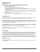
Parts List for All Precision Brew Models Models APB-330V2, APB-430V2, APBVSA-330V2, APBVSA-430V2, APBIC-330V2, APBIC-430V2 ITEM DESCRIPTION PART # Reference Front View Picture: 1 Controller PB 2 Relay, Heater* 3 Water Inlet Valve 24 VAC 4 Terminal Block 5 Spray Head 6 Orifice Bypass 6A Retaining Pin for A518-053 8 Switch Momentary ** PBIC only A530-066 A71450 A725-117 A531-035 APT400-105 A518-053 A551-098 A531-025 Reference Lower Warmer Picture: 20 Faucet Hot Water 21 Light Warmer 22 Switch Warmer 23 H
Front View (refer to key on page 27) 2 6 5 1* 7 4 3 Lower Warmer (refer to key on page 27) (APB-430V2 pictured) 23 23 21 21 22 Page 28 20 22 Shuttle Brewers & Airpot/Shuttle Brewers
Top View (refer to key on page 27) 36 38 35 36 35 42 32 34 30 52 Tank Lid (refer to key on page 27) 3 Heater Model shown 52 51 50 50 Shuttle Brewers & Airpot/Shuttle Brewers Page 29
Shuttle Parts List for APB-330V2 and APB-430V2 6 5 4 3 2 1 ITEM DESCRIPTION PART # 1 Faucet Model ES A537-053 2 Shank w/ Chrome Bonnet A522078 3 Gauge Assembly A718-018 4 Kit, Shuttle Lid A725-092 S.S. Shuttle Cover (not shown)* A713-027 5 Lid Retaining Clip A548-142 6 Lid Stopper w/ O-Ring A548-140 A61365 * S.S.
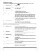
ITEM NO. 1 2 3 4 5 6 7 8 9 Shuttle Brewers & Airpot/Shuttle Brewers Title Stand Body Tray for Stand Vacuum Shuttle Stand Base Tray Top Self-Tapping Screw .5" Rubber Foot Plastic Insert Self-Tapping Scres .75" 2 5 1 6 9 4 8 PART NUMBER A548-157 A548-159 VS-1.5 A548-158 A517-018 A539-217 A548-161 A548-162 A539-218 3 7 VS-1.5S VS-1.5S/QTY. 1 1 1 1 1 4 4 3 3 4 ITEM NO.
Cleaning & Sanitizing Instructions for Model VS-1.5(S) These cleaning and sanitizing instructions are only a guideline to be used for the cleaning and sanitizing of the VS-1.5S and VS-S with VS-1.5. In-house cleaning and sanitizing methods may be more effective. Grindmaster assumes no responsibility for the food born illness and/or sickness caused by using improper sanitizing methods. For cleaning and sanitizing of the VS-1.5S and VS-S with VS-1.5 the three-sink method is recommended.
Wiring Diagram - Precision Brew 430 Series Models APB-430V2, APBVSA-430V2, and APBIC-430V2 Shuttle Brewers & Airpot/Shuttle Brewers Page 33
Wiring Diagram - Precision Brew 330 Series Models APB-330V2, APBVSA-330V2, and APBIC-330V2 Page 34 Shuttle Brewers & Airpot/Shuttle Brewers
Wiring Diagram APB-430V2E230, APBVSA-430V2E230, APBIC-430V2E230 (Single or Three Phase Models) Shuttle Brewers & Airpot/Shuttle Brewers Page 35
Wiring Diagram APB-330V2E230, APBVSA-330V2E230, APBIC-330V2E230 Brewers Page 36 Shuttle Brewers & Airpot/Shuttle Brewers
Wiring Diagram - Precision Brew 430 Series 120/208 or 120/240V Models APB-430V2, APBVSA-430V2, and APBIC-430V2 :+7 / %/. 3% 02'(/6 / 9 :505 (/(07 7(50,1$/ %/2&. 237,21$/ 0$67(5 32:(5 / / / 1 / / / 32:(5 6833/< %/. 6(( :$50(5 &,5&8,7 ',$* / 6(( +($7(5 &21),*6 21 27+(5 6+((7 &217$&725 1 :+7 %/. :$50(5 6:,7&+ %/. :+7 %51 9 :+7 :+7 %/. :$50(5 /,*+7 :+7 %/. :$50(5 6:,7&+ %/. 9 :505 (/(07 %/. :$50(5 /,*+7 :+7 +, 7(03 /,0,7 7+(50267$7 W %51 %51 %/. %/.
Wiring Diagram - Precision Brew 330 Series 120/208V, 120/240V Models APB-330V2, APBVSA-330V2, and APBIC-330V2 :+7 / / %/. &217$&725 237,21$/ 0$67(5 32:(5 7(50,1$/ %/2&. / 1 / / 32:(5 6833/< / 7$1. +($7(5 %/. %51 :+7 6(( :$50(5 &,5&8,7 ',$* 9 :+7 3% 02'(/6 9 :505 (/(07 +, 7(03 /,0,7 7+(50267$7 W %51 %/. %/. 9$ 75$16)250(5 &20 / %/. 1 :+7 %51 %/. %/.
Wiring Diagram 230V, 208V, or 240V without Neutral Models APB-430V2, APBVSA-430V2, APBIC-430V2, APB-430V2E230, APBVSA-430V2E230, and APBIC-430V2E230 :+7 / / %/. 3% 02'(/6 25 9 :505 (/(07 237,21$/ 0$67(5 32:(5 6(( +($7(5 &21),*6 21 27+(5 6+((7 &217$&725 7(50,1$/ %/2&. 1 / / / %/. / / / 32:(5 6833/< 6(( :$50(5 &,5&8,7 ',$* / %51 :+7 / %/. :+7 %/. %/. :$50(5 6:,7&+ :$50(5 /,*+7 :+7 25 9 :505 (/(07 %/. 9 9 :+7 %/. :$50(5 6:,7&+ %/.
Wiring Diagram 230V, 208V, or 240V without Neutral Models APB-330V2, APBVSA-330V2, APBIC-330V2, APB-330V2E230, APBVSA-330V2E230, APBIC-330V2E230 :+7 %/. / / &217$&725 237,21$/ 0$67(5 32:(5 7(50,1$/ %/2&. / 1 / / 32:(5 6833/< / 7$1. +($7(5 %/. %51 :+7 6(( :$50(5 &,5&8,7 ',$* 9 9 :+7 3% 02'(/6 25 9 :505 (/(07 +, 7(03 /,0,7 7+(50267$7 %51 W / %51 / %/. :+7 %/. %/. :$50(5 6:,7&+ :$50(5 /,*+7 :+7 9$ 75$16)250(5 RU %/. %/.
Wiring Diagram - Heater Configuration (3 Heater) Shuttle Brewers & Airpot/Shuttle Brewers Page 41
Wiring Diagram - Heater Configuration (1 Heater) Page 42 Shuttle Brewers & Airpot/Shuttle Brewers
Control Board all PrecisionBrew™ V2.0 models Refers to software version number. Subject to change.
Tel (502) 425-4776 • Fax (502) 425-4664 • 1-800-695-4500 (USA & Canada only) P.O. Box 35020 • Louisville, KY 40232 • USA www.grindmaster.com • email: info@grindmaster.