OPERATING MANUAL AND PARTS LIST MODEL GR254CTS COMPRESSOR Because quality work demands quality tools Distributed By PRIMESOURCE BUILDING PRODUCTS, INC.
TABLE OF CONTENTS Table of Contents .......................................................................... 1 Safety Symbols ............................................................................. 2 Safety Instructions........................................................................ 3 Specifications................................................................................ 5 Compressor Description ..............................................................
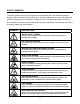
SAFETY SYMBOLS The safety symbols used on the compressor’s safety labels and in this manual provide an important visual reminder of basic safety rules, and the hazards that may arise if all safety and operating instructions are not followed. Make sure you understand the meaning of each of these symbols, and protect yourself and others by obeying all safety and operating instructions on warning labels and in this manual.
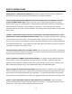
SAFETY INSTRUCTIONS WEAR ANSI Z87.1 APPROVED EYE PROTECTION - Always wear approved eye protection equipment that provides both front and side eye protection when operating or servicing the compressor. DO NOT EXCEED MAXIMUM RECOMMENDED OPERATING PRESSURE OF AIR-POWERED TOOLS OR OTHER EQUIPMENT BEING USED - Spray guns and other low to medium pressure equipment can burst, causing serious injury to user and bystanders.
SAFETY INSTRUCTIONS NEVER DIRECT COMPRESSED AIR AT ANY BODY PARTS - Compressed air can penetrate skin, or force dirt and debris into eyes, causing serious injury. Never place hands or body parts over the air discharge opening of a pressurized nozzle or fitting. Use care when connecting and disconnecting air hose to attachments, pneumatic tools, and other air-powered devices.
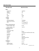
SPECIFICATIONS DESCRIPTION SPECIFICATION Motor Horsepower Voltage Amperage Hz Phase RPM 2.5(Peak) 120 14 60 Single 3450 Capacity Tanks Air Storage Capacity Maximum Air Pressure CFM 2 4.3 Gallons 125 PSI 4.
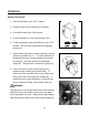
COMPRESSOR DESCRIPTION 1 7 6 4 2 5 4 3 18 2 8 17 9 16 10 15 11 14 5 GR254CTS 13 12 6
COMPRESSOR PARTS DESCRIPTION KEY DESCRIPTION FUNCTION 1 Handle Used to lift, carry, and position unit.
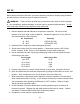
SET UP Before being used for the first time, your new compressor requires a simple set-up procedure that will help your unit deliver years of trouble-free service. WARNING: Failure to follow all initial set-up instructions may result in serious damage to your compressor, property damage, or serious injury to operator and bystanders. Do not start compressor until all set-up steps have been performed. 1. Remove dipstick and add lubricant to compressor crankcase.
OPERATION Starting Compressor 1. Push On/Off button to the "OFF" position. 2. Plug the power cord into the power receptacle. 2. Pull On/Off button to the "ON" position. 3. Leave compressor in “ON” position while in use. 4. To stop compressor, push On/Off button to the "OFF" position. DO NOT stop compressor by unplugging power cord. 5. Adjust outlet air pressure to desired setting by turning pressure regulator knob “C.” Turn knob clockwise to increase air pressure, counterclockwise to decrease air pressure.
MAINTENANCE Maintenance Schedule DANGER Never perform maintenance on the compressor when it is in the “ON” position. Always place On/Off switch in “OFF” position, disconnect power cord from power source, drain air tanks, and allow unit to cool first. Performing service procedures on a compressor with pressurized tanks, or that is in the “ON” position, can result in serious injury. Interval Maintenance Required 1st 50 Hrs. Drain lubricant from crankcase and replace.
COMPRESSOR SCHEMATIC - PUMP 11
COMPRESSOR PARTS LIST - PUMP REF NO. QTY. PART# 13 14 15 16 Head Bolt Head Intake filter Head Gasket Valve Plate Gasket Reed Valve Valve Plate Gasket Cylinder Bolt Gasket Comp.
COMPRESSOR PARTS LIST - PUMP REF NO. DESCRIPTION QTY.
COMPRESSOR PARTS LIST - TANK REF NO. DESCRIPTION QTY.
TROUBLESHOOTING PROBLEM Compressor won't start CAUSE REMEDY Circuit breaker tripped Reset breaker Fuse blown Replace fuse. Use Fusetron type “T” fuse only. Power turned off. Turn power on Pressure release valve on motor/pressure switch has not unloaded pump head pressure. Bleed line by moving switch to “OFF” position. Pull switch to “ON” position to restart unit. Defective cord or plug Replace Motor thermal overload tripped Turn compressor off, allow motor to cool, and reset overload button.
TROUBLESHOOTING PROBLEM CAUSE REMEDY Air leaks at fittings Fittings loose Tighten fittings Air leaks at compressor head Head bolts loose Tighten bolts securely Air blows out of inlet filter Damaged reed valve Have unit serviced by authorized service dealer Insufficient pressure at air tool or accessory Air intake filter dirty Clean or replace filter Air leaks Check unit for leaks and correct as needed. Air hose too small or too long Use large diameter air hose and larger capacity fittings.
MAINTENANCE PROCEDURES Check safety valve Check/clean air filter Drain water from tanks Check oil level STORAGE ! Open tank drain valve and allow all air pressure to escape. ! Drain all moisture out of tanks, and close drain valves. ! Disconnect air hose and wind hose carefully for storage ! Inspect compressor for wear, damage, or missing parts, and have repairs made promptly. ! Store unit in a dry, cool place.
PRIMESOURCE ® BUILDING PRODUCTS, INC. An Itochu Company PNEUMATIC TOOL/COMPRESSOR WARRANTY Pneumatic nailers, staplers & compressors marketed under the GRIP RITE TM brand are warranted to be free from defects in workmanship & materials (except rubber o-rings, bumpers, seals, driver blades, dipsticks, & air filters) for a period of one year from the date of original purchase.
PRIMESOURCE BUILDING PRODUCTS, INC.
MANUAL DE OPERACIÓN Y LISTA DE PIEZAS COMPRESOR MODELO GR254CTS Porque el trabajo de calidad requiere herramientas de calidad Distribuido por PRIMESOURCE BUILDING PRODUCTS, INC.
ÍNDICE Índice .......................................................................... .................. 1 Símbolos de seguridad ........................................................ ........ 2 Instrucciones de seguridad.......................................................... 3 Especificaciones ............................................................ .............. 5 Descripción del compresor ................................................ ........ 6 Descripción de las piezas del compresor.....
SÍMBOLOS DE SEGURIDAD Los símbolos de seguridad usados en las etiquetas de seguridad del compresor y en este manual constituyen un recuerdo visual importante de las reglas de seguridad básicas y de los peligros que pueden surgir si no se respetan todas las instrucciones de seguridad y operación.
INSTRUCCIONES DE SEGURIDAD LLEVE PUESTOS PROTECTORES PARA LOS OJOS APROBADOS POR ANSI Z87.1 – Lleve siempre equipos aprobados para la protección de los ojos tanto delanteros como laterales para hacer funcionar el compresor o efectuar el servicio del mismo.
INSTRUCCIONES DE SEGURIDAD NO DIRIJA NUNCA AIRE COMPRIMIDO A NINGUNA PARTE DEL CUERPO - El aire comprimido puede penetrar la piel o forzar la suciedad y los residuos dentro de ojos, ocasionando lesiones graves. No coloque nunca las manos ni las partes del cuerpo sobre la abertura de descarga de aire de una boquilla o conexión a presión. Tenga cuidado al conectar y desconectar la manguera de aire de los accesorios, herramientas neumáticas y otros dispositivos neumáticos.
ESPECIFICACIONES DESCRIPCIÓN ESPECIFICACIÓN Motor Potencia Voltaje Amperaje Hz Fase RPM Capacidad 2.5 hp (máxima) 120 14 60 Monofásica 3450 Depósitos Capacidad de almacenamiento de aire Presión de aire máxima PIE3/MIN 2 4.3 galones (16.3 litros) 125 lb/pulg2 (8.6 bares) 4.1 pie3/min a 90 lb/pulg2 4 pie3/min a 100 lb/pulg2 Ajustes del interruptor de presión Interruptor de presión - ENCENDIDO Interruptor de presión - APAGADO Bomba del compresor Cilindros Etapa de compresión Lubricación 95 lb/pulg2 (6.
DESCRIPCIÓN DEL COMPRESOR 1 7 6 4 2 5 4 3 18 2 8 17 9 16 10 15 11 14 5 GR254CTS 13 12 6
DESCRIPCIÓN DE LAS PIEZAS DEL COMPRESOR CLAVE DESCRIPCIÓN FUNCIÓN 1 Asa Se usa para levantar, llevar y colocar la unidad.
CONFIGURACIÓN Antes de usarse por primera vez, el nuevo compresor requiere un procedimiento de configuración sencillo que permitirá que la unidad funcione a buen rendimiento y sin problemas durante años. ADVERTENCIA: De no seguir todas las instrucciones de configuración iniciales, se pueden producir daños importantes en el compresor, daños materiales o el operador o las personas de los alrededores pueden resultar gravemente lesionadas.
OPERACIÓN Arranque del compresor 1. Ponga el botón de encendido/apagado en la posición “OFF”. 2. Enchufe el cordón de alimentación a la toma de corriente. 3. Ponga el botón de encendido/apagado en la posición “ON”. 4. Deje el compresor en la posición “ON” mientras se usa. 5. Para detener el compresor, ponga el botón de encendido/apagado en la posición “OFF”. NO pare el compresor desenchufando el cordón de alimentación. 6.
MANTENIMIENTO Plan de mantenimiento PELIGRO No efectúe nunca tareas de mantenimiento en el compresor cuando esté en la posición “ON”. Ponga siempre el interruptor de encendido/apagado en la posición “OFF”, desconecte el cordón de alimentación de la fuente de alimentación, desagüe los depósitos de aire y deje enfriarse primero la unidad. Al efectuar procedimientos de servicio en un compresor con depósitos a presión, es decir, en la posición “ON”, se pueden producir lesiones graves.
ESQUEMA DEL COMPRESOR - BOMBA 11
LISTA DE PIEZAS DEL COMPRESOR - BOMBA N° DE REF.
LISTA DE PIEZAS DEL COMPRESOR - BOMBA N° DE REF. DESCRIPCIÓN 29 30 31 32 33 34 35 Cojinete Cubierta de extremo Ventilador Perno pasante Envuelta Arandela Tornillo 36 Juego de empaquetaduras – incluye las piezas siguientes: GRFC4, GRFC34, GRFC35, GRFC43, GRFC44 ESQUEMA DEL COMPRESOR - DEPÓSITOS 13 CDAD.
LISTA DE PIEZAS DEL COMPRESOR - DEPÓSITOS N° DE REF.
RESOLUCIÓN DE PROBLEMAS PROBLEMA El compresor no arranca. CAUSA SOLUCIÓN Disyuntor disparado. Reajuste el disyuntor. Fusible fundido. Reemplace el fusible. Use un fusible de tipo “T” Fusetron solamente. Corriente apagada. Encienda la corriente. La válvula de alivio de presión en el interruptor del motor/presión no ha descargado la presión de la cabeza de la bomba. Purgue la tubería moviendo el interruptor a la posición “OFF”.
RESOLUCIÓN DE PROBLEMAS PROBLEMA CAUSA SOLUCIÓN Nivel de aceite bajo. Compruebe los requisitos de pie3/min de la herramienta o del accesorio neumático que se está usando. Desgaste o daño interno. Compruebe si hay fugas y agregue aceite. Fugas de aire en la válvula de desprendimiento del interruptor del motor/presión mientras funciona el motor. Interruptor que no funciona. Pida a un distribuidor de servicio autorizado que repare la unidad.
PROCEDIMIENTOS DE MANTENIMIENTO Compruebe la válvula de seguridad. Compruebe/limpie el filtro Desagüe el agua de los de aire. depósitos. Compruebe el nivel de aceite. ALMACENAMIENTO ! Abra la válvula de desagüe del depósito y deje que se escape toda la presión de aire. ! Vacíe toda la humedad de los depósitos y cierre las válvulas de desagüe. ! ! Desconecte la manguera de aire y enróllela con cuidado para guardarla.
PRIMESOURCE ® BUILDING PRODUCTS, INC. Una compañía Itochu GARANTÍA PARA HERRAMIENTAS NEUMÁTICAS/COMPRESORES Se garantiza que las clavadoras, las grapadoras y los compresores neumáticos distribuidos comercialmente con la marca GRIP RITE™ no tienen defectos de fabricación y materiales (excepto las juntas tóricas de caucho, topes, sellos, hojas de impulsor, varillas de medición y filtros de aire) durante un período de un año contado a partir de la fecha original de compra.
PRIMESOURCE BUILDING PRODUCTS, INC.