OPERATING MANUAL AND PARTS LIST MODEL GR55G10X/GR90G10X COMPRESSORS www.grip-rite.
TABLE OF CONTENTS Table of Contents .......................................................................... 1 Safety Symbols ............................................................................. 2 Safety Instructions........................................................................ 3 Specifications................................................................................ 5 Compressor Description ..............................................................
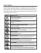
SAFETY SYMBOLS The safety symbols used on the compressor’s safety labels and in this manual provide an important visual reminder of basic safety rules, and the hazards that may arise if all safety and operating instructions are not followed. Make sure you understand the meaning of each of these symbols, and protect yourself and others by obeying all safety and operating instructions on warning labels and in this manual.
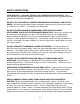
SAFETY INSTRUCTIONS WEAR ANSI Z87.1 (In Canada, CSA Z94.3-99) APPROVED EYE PROTECTION - Always wear approved eye protection equipment that provides both front and side eye protection when operating or servicing the compressor. DO NOT START OR OPERATE COMPRESSOR INDOORS OR IN POORLY VENTILATED AREAS - Gasoline engine produce carbon monoxide, a poisonous gas that can cause death or serious injury if inhaled. Use compressor outdoors only.
SAFETY INSTRUCTIONS DO NOT TAMPER WITH COMPRESSOR PRESSURE SWITCH SETTINGS - The pressure switch settings set at the factory provide the maximum safe operating pressure recommended for this compressor. Altering these settings can result in over-pressurization, risk of tank, hose, and pneumatic equipment failure, and serious injury to operator and bystanders. USE AIR HOSE RATED FOR 150 PSI OR GREATER - Air hose must be rated to safely handle maximum compressor pressure.
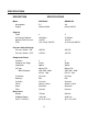
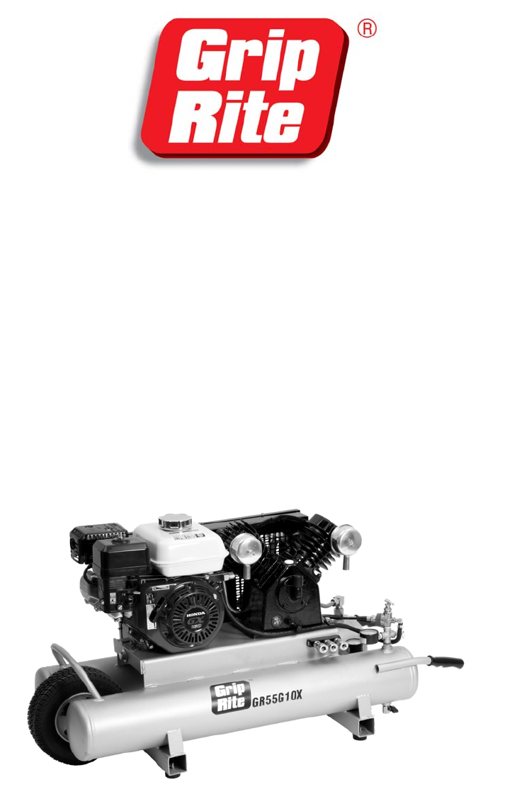
SPECIFICATIONS DESCRIPTION SPECIFICATIONS Motor Horsepower Engine GR55G10X 5.5 Honda GX160 GR90G10X 9.0 Honda GX270 Capacity Tanks Air Storage Capacity Maximum Air Pressure CFM 2 10 Gallons 135 PSI 12.5 cfm @ 100 PSI 2 10 Gallons 135 PSI 18.
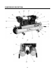
COMPRESSOR DESCRIPTION 6
COMPRESSOR PARTS DESCRIPTION KEY 1 2 3 4 5 6 7 8 9 10 11 12 13 14 15 16 17 18 19 20 21 22 23 24 25 DESCRIPTION Belt Guard Compressor Pump Compressor Air Intake Crankcase breather/fill plug Pilot Valve Tank Air Pressure Gauge Rubber Hand Grips Tank Drain Cock Quick Connect Fittings Pump Oil Drain Tube Oil Level Sight Glass Cushioned Rubber Foot Twin Air Storage Tanks No Flat Tire Easy Belt Tightening System Engine Fuel/Choke Controls Engine Air Filter Engine Exhaust Muffler Engine Fuel Tank Fuel Tank Cap En
SET UP PROCEDURE WARNING: Before being operated with pressurized tanks for the first time, your new compressor requires a simple set-up procedure that will help your unit deliver years of trouble-free service. Failure to follow all initial set-up instructions may result in serious damage to your compressor, property damage, or serious injury to operator and bystanders. Do not allow compressor to pressurize tanks until all set-up steps have been performed. 1. Read the entire engine manual. 2.
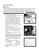
OPERATION STARTING ENGINE Pre-starting Checklist: Always check and correct before starting: Check unit for missing parts or damage. Check for loose nuts and bolts. Check compressor and engine oil levels. Fill gas tank. Tighten gas cap securely. Check for fuel leaks. 1. Move fuel lever (A) to the ON position. Cold Engine - move choke lever (B) to CLOSED position. Warm Engine - leave choke lever (B) in OPEN position 2. Turn engine switch (C) to the "ON" position. 3.
OPERATION NORMAL OPERATION Engine runs at normal running speed until maximum tank air pressure is reached. When maximum pressure is reached, engine speed automatically resets to idle. Engine speed remains at idle until tank pressure drops to the minimum air pressure setting. Engine continues cycling between normal and idle speed automatically until turned off.
MAINTENANCE Maintenance Schedule COMPRESSOR MAINTENANCE CHART Interval Maintenance Required Check compressor pump and engine lubricant levels, and fill as needed. Daily Weekly Drain moisture from tanks daily. Open drain slowly and let air pressure bleed down gradually before opening drain valve completely. Perform a visual inspection of compressor. Make sure belt guard is in place, and all components are in good condition.
GR55G10X COMPRESSOR SCHEMATIC- TANK / FRAME 12
GR55G10X COMPRESSOR PARTS LIST- TANK / FRAME REF NO. 1 DESCRIPTION Screw QTY. 5 GRCE1490 2 Belt Guard Cover 1 GRCE1160 3 Belt Guard Base 1 GRCE1140 4 Belt 1 GRCE1340 5 Bolt 1 GRCE1630 6 Washer 1 GRCE1640 7 Flywheel 1 GRCE1800 8 Complete Pump with Flywheel 1 GRCE840 9 Delivery Tube with Fittings 1 GRCE1420 10 Elbow 1 GRCE1290 11 Check Valve 1 GRCE1360 12 Elbow 1 GRCE1260 13 Tubing - 1/4” 1.2’ GRCE1100 14 Rubber Hose - 1/4” 2.
GR55G10X COMPRESSOR PARTS LIST- TANK / FRAME REF NO. 30 31 32 33 34 35 36 37 38 39 40 41 42 43 44 45 46 47 48 49 50 51 52 53 54 55 DESCRIPTION Hose Barb Washer -1/2" Handle Grip Drain Valve Triple Manifold Quick Coupler Tank Assembly Rubber Pad Screw Cotter Pin Machine Bushing Axle Wheel Belt Tensioner Kit Engine Drain Pipe Cap Element Intake Filter Assembly Keystock Pulley Setscrew Washer Bolt Idle Control Kit Clamp QTY.
GR55G10X COMPRESSOR PARTS LIST - PUMP 15
GR55G10X COMPRESSOR PARTS LIST - PUMP REF # 1 PART # GRCE130 DESCRIPTION QTY Intake Filter Assembly 2 2 GRCE50 Intake Element 2 3 GRCE520 Cylinder Head 2 4 GRCE570 Gasket 2 5 GRCE560 Gasket 2 6 GRCE1660 Triangle Valve Spring 2 7 GRCE210 Lift Limiter 4 8 GRCE550 Inlet Valve 2 9 GRCE1670 Outlet Valve 4 GRCE1680 Lock Screws (not shown) 12 10 GRCE1690 Valve Plate Assembly (items 4-9) 2 11 GRCE580 Cylinder 2 12 GRCE330 Gasket 2 13 GRCE100 Oil Fill Plug 1 1
GR90G10X COMPRESSOR SCHEMATIC- TANK / FRAME 17
GR90G10X COMPRESSOR PARTS LIST - TANK/FRAME REF NO. 1 DESCRIPTION Screw QTY. 5 GRCE1490 PART # 2 Belt Guard Cover 1 GRCE1170 3 Belt Guard Base 1 GRCE1150 4 Belt 1 GRCE1350 5 Bolt 1 GRCE1630 6 Washer 1 GRCE1640 7 Flywheel 1 GRCE1650 8 Complete Pump with Flywheel 1 GRCE850 9 Delivery Tube with Fittings 1 GRCE1430 10 Elbow 1 GRCE1290 11 Check Valve 1 GRCE1360 12 Elbow 1 GRCE1260 13 Tubing - 1/4” 1.2’ GRCE1100 14 Rubber Hose - 1/4” 2.
GR90G10X COMPRESSOR PARTS LIST - TANK/FRAME REF NO. 30 DESCRIPTION Hose Barb QTY.
GR90G10X COMPRESSOR SCHEMATIC - PUMP 20
GR90G10X COMPRESSOR PARTS LIST - PUMP REF # PART # DESCRIPTION QTY 1 GRCE130 Intake Filter Assembly 3 2 GRCE50 Intake Element 3 3 GRCE520 Cylinder Head 3 4 GRCE570 Gasket 3 5 GRCE560 Gasket 3 6 GRCE1660 Triangle Valve Spring 6 7 GRCE210 Lift Limiter 6 8 GRCE550 Inlet Valve 3 9 GRCE1670 Outlet Valve 6 GRCE1680 Lock Screws (not shown) 18 10 GRCE1690 Valve Plate Assembly 3 11 GRCE580 Cylinder 3 12 GRCE330 Gasket 3 13 GRCE100 Oil Fill Plug 1 14 GRCE110
TROUBLESHOOTING PROBLEM Compressor won't start Low pressure Oil in discharge Compressor overheats CAUSE REMEDY On/Off switch in OFF position Move switch to ON position Fuel Switch in OFF position Move switch to ON position Choke lever in Open Choke (running) position Move lever to Closed choke (starting) position Fuel tank empty Fill fuel tank Spark plug fouled Replace spark plug Motor air filter plugged Replace filter Other Refer to engine manufacturer’s manual Drain cock open or loose
TROUBLESHOOTING PROBLEM Compressor Loads/Unloads or Starts/Stops excessively Insufficient output - low discharge pressure Motor stalls Water in crankcase oil - Oil gets dirty, valves or cylinders get rusty. CAUSE REMEDY Leaks in air system Replace worn parts as necessary Worn or loose drive belts Tighten or replace belts as necessary.
TROUBLESHOOTING PROBLEM Excessive vibration Compressor knocks Compressor uses too much oil Piston rings not seated CAUSE REMEDY Loose compressor or motor Tighten mounting bolts Excessive discharge pressure Reduce operating pressure Compressor not level Level compressor Leg bolt tightened too tight Loose leg bolts Wrong oil being used Drain and replace with proper oil Loose flywheel, drive pulley, or drive belt Tighten parts and check belt tension. Tighten belt if needed.
TROUBLESHOOTING PROBLEM CAUSE REMEDY Tool, sprayer, or other accessory doesn't work properly. Air pressure too low or too high Adjust regulator to provide pressure recommended by product manufacturer. Unit runs continuously Air usage greater than compressor output capacity Check CFM requirements of air tool or accessory being used. Noisy operation Oil level low Check for leaks, and add oil Internal wear or damage Have unit serviced by authorized service dealer.
PRIMESOURCE ® BUILDING PRODUCTS, INC. and BUILDING PRODUCTS CANADA CORPORATION Are Itochu Companies PNEUMATIC TOOL/COMPRESSOR WARRANTY Pneumatic nailers, staplers & compressors marketed under the GRIP RITE TM brand are warranted to be free from defects in workmanship & materials (except rubber o-rings, bumpers, seals, driver blades, dipsticks, & air filters) for a period of one year from the date of original purchase.
GRGASMAN 03/09 27