MODEL G0440/G0441 2 HP & 3 HP CYCLONE DUST COLLECTORS OWNER'S MANUAL (For models manufactured since 03/12) Model G0441 Shown With Optional Stand COPYRIGHT © APRIL, 2005 BY GRIZZLY INDUSTRIAL, INC. REVISED FEBRUARY, 2019 (JL) WARNING: NO PORTION OF THIS MANUAL MAY BE REPRODUCED IN ANY SHAPE OR FORM WITHOUT THE WRITTEN APPROVAL OF GRIZZLY INDUSTRIAL, INC. #TR7027 PRINTED IN TAIWAN V7.02.
This manual provides critical safety instructions on the proper setup, operation, maintenance, and service of this machine/tool. Save this document, refer to it often, and use it to instruct other operators. Failure to read, understand and follow the instructions in this manual may result in fire or serious personal injury—including amputation, electrocution, or death. The owner of this machine/tool is solely responsible for its safe use.
Table of Contents INTRODUCTION................................................ 2 Machine Description....................................... 2 Contact Info.................................................... 2 Manual Accuracy............................................ 2 Identification.................................................... 3 G0440 Machine Data Sheet........................... 4 G0441 Machine Data Sheet........................... 6 SECTION 1: SAFETY........................................
INTRODUCTION Machine Description Manual Accuracy The Model G0440/G0441 is a 2-stage cyclone wood dust collector capable of collecting dust from multiple machines running simultaneously. We are proud to provide a high-quality owner’s manual with your new machine! Cyclonic action separates the heavy dust and chips from the fine particles and drops them into the steel collection drum. Any remaining fine dust travels past the impeller and is trapped by the pleated cartridge filter.
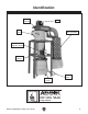
Identification Blower Housing Motor Inlet Port Canister Filter Assembly Remote Magnetic Switch Optional Stand Collection Drum Vacuum Hose Figure 1. Identification (Model G0441 shown with optional stand). To reduce your risk of serious injury, read this entire manual BEFORE using machine. Model G0440/G0441 (Mfg.
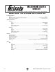
MACHINE DATA SHEET Customer Service #: (570) 546-9663 · To Order Call: (800) 523-4777 · Fax #: (800) 438-5901 MODEL G0440 2 HP CYCLONE DUST COLLECTOR Product Dimensions: Weight.............................................................................................................................................................. 287 lbs. Width (side-to-side) x Depth (front-to-back) x Height..................................................................... 59 x 38 x 93-1/2 in.
Main Specifications: Operation Dust Collector Type.......................................................................................................... Two-Stage (Cyclone) Approved Dust Types................................................................................................................................ Wood Filter Type............................................................................................................................... Pleated Cartridge Airflow Capacity.........
G0441 Machine Data Sheet MACHINE DATA SHEET Customer Service #: (570) 546-9663 · To Order Call: (800) 523-4777 · Fax #: (800) 438-5901 MODEL G0441 3 HP CYCLONE DUST COLLECTOR Product Dimensions: Weight.............................................................................................................................................................. 347 lbs. Width (side-to-side) x Depth (front-to-back) x Height............................................................. 60-1/4 x 38-1/2 x 109 in.
Main Specifications: Operation Dust Collector Type.......................................................................................................... Two-Stage (Cyclone) Approved Dust Types................................................................................................................................ Wood Filter Type............................................................................................................................... Pleated Cartridge Airflow Capacity.........
SECTION 1: SAFETY For Your Own Safety, Read Instruction Manual Before Operating This Machine The purpose of safety symbols is to attract your attention to possible hazardous conditions. This manual uses a series of symbols and signal words intended to convey the level of importance of the safety messages. The progression of symbols is described below. Remember that safety messages by themselves do not eliminate danger and are not a substitute for proper accident prevention measures.
WEARING PROPER APPAREL. Do not wear clothing, apparel or jewelry that can become entangled in moving parts. Always tie back or cover long hair. Wear non-slip footwear to reduce risk of slipping and losing control or accidentally contacting cutting tool or moving parts. HAZARDOUS DUST. Dust created by machinery operations may cause cancer, birth defects, or long-term respiratory damage. Be aware of dust hazards associated with each workpiece material.
Additional Safety for Dust Collectors INTENDED USE. This dust collector is designed for collecting wood dust and chips from woodworking machines. DO NOT use it to collect metal, dirt, drywall, asbestos, lead paint, silica, liquids, aerosols, biohazards, or explosive materials. Collecting the wrong materials can result in serious inhalation hazards, fire, or machine damage. HAZARDOUS DUST. Dust created while using machinery may cause cancer, birth defects, or long-term respiratory damage.
SECTION 2: POWER SUPPLY Availability Circuit Requirements Before installing the machine, consider the availability and proximity of the required power supply circuit. If an existing circuit does not meet the requirements for this machine, a new circuit must be installed. To minimize the risk of electrocution, fire, or equipment damage, installation work and electrical wiring must be done by an electrician or qualified service personnel in accordance with all applicable codes and standards.
Connection Type Grounding Instructions A permanently connected (hardwired) power supply is typically installed with wires running through mounted and secured conduit. A disconnecting means, such as a locking switch (see following figure), must be provided to allow the machine to be disconnected (isolated) from the power supply when required. This installation must be performed by an electrician in accordance with all applicable electrical codes and ordinances.
SECTION 3: SETUP Unpacking This machine presents serious injury hazards to untrained users. Read through this entire manual to become familiar with the controls and operations before starting the machine! Wear safety glasses during the entire setup process! This machine and its components are very heavy. Get lifting help or use power lifting equipment such as a forklift to move heavy items. This machine was carefully packaged for safe transport.
G0440 Inventory B C The following is a list of items shipped with your machine. Before beginning setup, lay these items out and inventory them. A If any non-proprietary parts are missing (e.g. a nut or a washer), we will gladly replace them; or for the sake of expediency, replacements can be obtained at your local hardware store. Inventory (Figure 2) Qty A. Intake Cylinder............................................ 1 B. Cyclone Funnel........................................... 1 C. Intake Barrel.......
G0441 Inventory B C The following is a description of the main components shipped with your machine. Lay the components out to inventory them. Inventory: (Figure 3) Qty A. Intake Cylinder............................................ 1 B. Cyclone Funnel........................................... 1 C. Intake Barrel................................................ 1 D. Canister/Drum Collection Bags.......... 1 Each E. Gray Flexible Hose 8" x 20"........................ 1 F. Motor/Blower Housing Assembly.......
Site Considerations Weight Load Physical Environment Refer to the Machine Data Sheet for the weight of your machine. Make sure that the surface upon which the machine is placed will bear the weight of the machine, additional equipment that may be installed on the machine, and the heaviest workpiece that will be used. Additionally, consider the weight of the operator and any dynamic loading that may occur when operating the machine.
Wall Mounting Wood Framed Walls, G0440 = Lag Bolts = Lag Bolts, Countersunk Before mounting, make sure you locate your dust collector away from any open flames or potential ignition sources, as fine dust can easily ignite. 36" If you are mounting your dust collector to a wood framed wall, you must build and install the wall mounting boards described below to support the heavy weight of the dust collector. 31⁄2" If you are mounting your dust collector to a concrete or masonry wall, skip to Page 18.
2. Copy the mounting hole layout pattern from the motor housing (see Figures 7–8) to your wall mounting board, making sure the Top Row Mounting Hole Height is correct for your dust collector. Top Row Mounting Hole Height Use these measurements for hole placement when mounting the Model G0440. 201⁄2" 10 ⁄4" 80" Floor 73⁄4" Ø0.55" 10 ⁄4" 1 1 Wall Stud Centers G0440 Motor Housing Figure 9. Board fastened to wall and ready for G0440 motor/blower housing assembly.
Assembly 3. Attach the intake cylinder to the bottom of the housing, as shown in Figure 11, using (4) 5 ⁄16"-18 x 3⁄4" hex bolts and (4) 5⁄16" flat washers. Note: Because this part of the dust collector will not be accessible after assembly, consider using medium strength thread locking compound on the bolts that secure the intake cylinder to the motor/blower housing assembly. This added measure will ensure that the fasteners will not come loose from vibration.
5. Place the intake barrel brace in position and mark the location of the mounting holes (shown in Figure 13) with a small pencil, nail, or push pin. 8. Mounting Hole Locations Attach the cyclone funnel to the intake barrel with a barrel gasket between them, as shown in Figure 15, using (12) 5⁄16"-18 x 1" hex bolts, (24) 5⁄16" flat washers, and (12) 5⁄16"-18 hex nuts; also secure the wall mounting brace to the lip of the intake barrel/funnel assembly with the same hardware.
11. Attach the outlet port and filter L-braces to the blower housing with the outlet gasket between the outlet port and the housing, as shown in Figures 17–18, using (8) 5⁄16"-18 x 1" hex bolts, (16) 5⁄16" flat washers, and (8) 5 ⁄16"-18 hex nuts. 12. Mount the filter to the L-braces with the brace gaskets between them, as shown in Figure 19, using (4) 5⁄16"-18 x 3⁄4" hex bolts and (4) 5 ⁄16" fender washers.
b. Connect the gray flexible hose from the outlet port to the canister adapter and secure it in place with the two 7" hose clamps, as shown in Figure 21. b. Attach the 8" x 5" gray flexible hose between the canister adapter and the muffler with two 8" hose clamps, then attach the 8" x 20" gray flexible hose between the muffler and the outlet port with the remaining two 8" hose clamps (see Figure 23).
Note—For the Model G0441 Only: If you plan to keep your machine under an 8' ceiling, skip Step 15. 15. Model G0441: Connect the upper and lower collection drums together and secure them with the included metal clamp and provided fasteners, as shown in Figure 25. Figure 26. Installing drum latches on collector drum. 17. Place the collection drum vacuum ring on the bottom of the collection drum (see Figure 27).
18. Insert the rubber seal over the top lip of the collection drum rim. Pay special attention to the direction of the seal, as shown in the Figure 28. 20. Move the collector drum under the dust collector and connect it to the cyclone funnel with the clear flexible hose and the two 9" hose clamps, as shown in Figure 30. Tip: To keep the seal in place, you can use an adhesive applied to the rubber seal at approximately 1" intervals. Seal Optional Adhesive Drum Rim Figure 28. Installing canister seal. 19.
22. Fit the plastic canister collection bag over the bottom of the canister filter and clamp in place with the metal bag clamp, as shown in Figure 32. Test Run Once the assembly is complete, test run your machine to make sure it runs properly and is ready for regular operation. If, during the test run, you cannot easily locate the source of an unusual noise or vibration, stop using the machine immediately, then review the Troubleshooting on Page 41.
SECTION 4: DESIGNING THE SYSTEM General Always guard against static electrical build up by grounding all dust collection lines. The Model G0440/G0441 works great as a central system for a small shop or a dedicated dust collector for large production machines. When installing the dust collector be sure to put it in an out of the way location such as a corner or separate room. The dust collector is capable of collecting dust from up to three machines running simultaneously.
Metal Duct Flexible Duct Advantages of metal duct is its conductivity and that it does not contribute to static electrical charge build-up. However, static charges are still produced when dust particles strike other dust particles as they move through the duct. Since metal duct is a conductor, it can be grounded quite easily to dissipate any static electrical charges. Flexible hose is generally used for short runs, small shops and at rigid duct-to-tool connections.
System Design Step 1. Decide Who Will Design For most small-to-medium sized shops, you can design and build the dust collection system yourself without hiring engineers or consultants. We have included some basic information here to get you started on a basic design. If you have a large shop or plan to design a complicated system, we recommend doing additional research beyond this manual or seeking the help of an expert. Step 2.
3. Directional changes should be kept to a minimum. The more directional change fittings you use directly increases the overall resistance to airflow. 4. Gradual directional changes are more efficient than sudden directional changes (i.e. use the largest corner radius possible when changing hose or pipe direction). 5. Each individual branch line should have a blast gate immediately after the branch to control suction from one machine to another. 6.
Experiment with different combinations of blast gates open/closed to find the best results for your system. Determining Main Line Duct Size The general rule of thumb for a main line duct is that the velocity of the airflow must not fall below 3500 FPM. For small/medium sized shops, using the inlet size of the dust collector as the main line duct size will usually keep the air velocity above 3500 FPM and, depending on your system, will allow you to keep multiple branches open at one time.
Multiple Dust Ports Duct Dia. Approximate Static Pressure Loss Per Foot of Rigid Pipe Approximate Static Pressure Loss Per Foot of Flex Pipe Main Lines at 3500 FPM Branch Lines at 4000 FPM Main Branch Lines Lines at 3500 at 4000 FPM FPM 2" 0.091 0.122 0.35 0.453 Two Machines on Same Branch Line 2.5" 0.08 0.107 0.306 0.
3. 5. Add the additional factors from the following table to your list. Additional Factors G0440 MACHINE Example: A typical Data Sheet Performance Curve is illustrated in Figure 49. Find 4.4 on DATA SHEET the Static Pressure axis (the amount of total Static Pressure Seasoned (well used) 1" Dust Collection Filter Compare the total static pressure loss for that line to the closest CFM given in Figure 50 for your dust collector on Page 34.
Example Materials List G0440 Performance Curve 2500 2250 2000 1750 1500 1250 1000 750 500 250 0 After the system is designed, create a materials list of all the items you will need to build your dust collection system. This will make it easy when it comes time to purchase the materials. 1354 Below is an example of some items that might be needed. Refer to Accessories for dust collection components available through grizzly.com. 0.0 1.0 2.0 3.0 4.0 5.0 6.0 7.0 8.0 9.0 10.0 11.
System Grounding Since plastic hose is abundant, relatively inexpensive, easily assembled and air tight, it is a very popular material for conveying dust from woodworking machines to the dust collector. We recommend using flexible hose (flex-hose) to connect the woodworking machine to the dust collector. However, plastic flex-hose and plastic duct are an insulator, and dust particles moving against the walls of the plastic duct create a static electrical build up.
SECTION 5: OPERATIONS Remote Control To reduce your risk of serious injury, read this entire manual BEFORE using machine. To reduce risk of eye injury from flying chips or lung damage from breathing dust, always wear safety glasses and a respirator when operating this machine. The remote control for the Model G0440/G0441 is IR (infrared) rather than RF (radio frequency) to prevent accidental startups by other common RF items, such as garage door openers.
ACCESSORIES SECTION 6: ACCESSORIES Installing unapproved accessories may cause machine to malfunction, resulting in serious personal injury or machine damage. To reduce this risk, only install accessories recommended for this machine by Grizzly. H5294—4" Metal Duct Machine Addition Kit H5296—5" Metal Duct Machine Addition Kit H5298—6" Metal Duct Machine Addition Kit Save over 20% with this great machine addition kit.
G6163—4" Clamp G7343—5" Clamp G7361—6" Clamp H5228—7" Clamp H5238—8" Clamp H5253—9" Clamp These clamps feature lever latches and foam seals, and secure around the rolled ends of fittings and pipe. Figure 57. Dust collection pipe clamp. G2752—4" Rolling Floor Sweep G2753—4" Bench Dust Collection Attachment G2754—4" Floor Dust Collection Attachment These attachments are indispensable for collecting dust at machines without a port.
SECTION 7: MAINTENANCE Cleaning Filter Always disconnect power to the machine before performing maintenance. Failure to do this may result in serious personal injury. Emptying Drum Your new cyclone dust collector has a gentle brush system inside the filter for cleaning. This brush system is controlled by the red and black handles shown in Figure 61. Red Handle Empty the collection drum when it is no more than 3 ⁄4 full.
Removing/Replacing Filter 4. Remove the canister assembly from the dust collector and place it right-side up on a stable, flat surface. 5. Remove the six hex bolts, hex nuts, and flat washers from the rim of the canister base, as shown in Figure 63. The filter inside the canister assemblies can be removed from the assembly so that it can be replaced or rinsed off. Removing/installing the filter requires removing the canister filter assembly from the dust collector and disassembling it.
7. Carefully lift the filter out of the canister assembly, as shown in Figure 65. 9. Re-insert a filter into the canister assembly. Note: Make sure the bristles of the brush are straight to ensure efficient cleaning of the filter when needed. 10. Re-attach the canister base in the reverse order that you removed it. 11. Re-attach the canister assembly to the dust collector, then re-install a fresh collection bag with the bag clamp. Figure 65. Removing the filter from the canister assembly. 8.
SECTION 8: SERVICE Review the troubleshooting procedures in this section if a problem develops with your machine. If you need replacement parts or additional help with a procedure, call our Technical Support. Note: Please gather the serial number and manufacture date of your machine before calling. Troubleshooting Symptom Possible Cause Possible Solution Motor will not start, or it growls on start up. 1. Power supply fuse or circuit breaker has tripped. 2. Toggle switch is broken inside. 3.
SECTION 9: WIRING These pages are current at the time of printing. However, in the spirit of improvement, we may make changes to the electrical systems of future machines. Compare the manufacture date of your machine to the one stated in this manual, and study this section carefully. If there are differences between your machine and what is shown in this section, call Technical Support at (570) 546-9663 for assistance BEFORE making any changes to the wiring on your machine.
G0440 Wiring Diagram Ground 1-PHASE 220 VAC Hot DISCONNECT SWITCH (as recommended) 1 2 Run Capacitor 50µF 250VAC Hot Start Capacitor 300MFD 125VAC 220V Motor OL_NO A1 1L1 3L2 5L3 A2 13NO AC OUT AC IN 220V Circuit Board Ground NHD C-12D 2T1 4T2 6T3 14NO A2 14 O 13 11 98 12 97 96 R 95 NHD NTH-14 2T1 4T2 6T3 ON/OFF Switch 220V Magnetic Contactor Switch and Overload Relay Model G0440/G0441 (Mfg.
G0441 Wiring Diagram Ground 1-PHASE 220 VAC Hot DISCONNECT SWITCH (as recommended) 1 2 Run Capacitor 60µF 300VAC Hot Start Capacitor 600MFD 125VAC 220V Motor OL_NO A1 1L1 3L2 5L3 A2 13NO AC OUT AC IN 220V Circuit Board Ground NHD C-18D 2T1 4T2 6T3 14NO A2 25 O 24 21 98 23 97 96 R 95 NHD NTH-25 2T1 4T2 6T3 ON/OFF Switch 220V Magnetic Contactor Switch and Overload Relay -44- READ ELECTRICAL SAFETY ON PAGE 42! Model G0440/G0441 (Mfg.
G0440/G0441 Electrical Components CONNECTION 2 1 220V Motor Wiring Figure 67. Motor wiring. Figure 68. Motor wiring schematic. Magnetic Switch Contactor Circuit Board Overload Relay Junction Box Figure 69. G0441 magnetic switch assembly. Model G0440/G0441 (Mfg.
g SECTION 10: PARTS G0440 Main 1-3 1-1 1-2 1-6 1-5 1-4 1-7 95 3V3-4 20 19 9 77 11 10 15 16 18V2 4 3V3 3V3-3 96 60 65 21 22 79 25 24 35 37 38 40 28 36 23 61 42 64 45 46 41 Connections: 66 67 DUTY HEAT WEIGHT CLASS DATE SER. NO.
G0440 Parts List REF PART # DESCRIPTION REF PART # DESCRIPTION 1 1-1 1-2 1-3 1-4 1-5 1-6 1-7 1-8 1-9 1-10 2 3V3 3V3-1 3V3-2 3V3-3 3V3-4 4 5 6 7 8 9 10 11 12 13 14A 15 16 17 18V2 19 20 21 22 23 24 25 26 27 28 28-1 29 30 31 32V3 32V3-1 32V2-2 32V2-3 32V2-4 32V2-5 34V2 35 36 37 38 P0440001 P0440001-1 P0440001-2 P0440001-3 P0440001-4 P0440001-5 P0440001-6 P0440001-7 P0440001-8 P0440001-9 P0440001-10 P0440002 P0440003V3 P0440003V3-1 P0440003V3-2 P0440003V3-3 P0440003V3-4 P0440004 P0440005 P0440006 P044000
G0441 Main 1-3 1-1 1-2 1-6 1 1-5 1-4 1-7 5 8 1-8 1-10 1-9 13 12 86 20 19 9 84 11 10 18A 7 6 17 2 14A 15 16 95 3V3-1 3V3-2 3V3-4 21 85 3V3 25 24 35 38 3V3-3 4 67 29 42 Grizzly Cyclone Induction Motor DUTY HEAT WEIGHT CLASS DATE SER. NO.
G0441 Parts List REF PART # DESCRIPTION 1 1-1 1-2 1-3 1-4 1-5 1-6 1-7 1-8 1-9 1-10 2 3V3 3V3-1 3V3-2 3V3-3 3V3-4 4 5 6 7 8 9 10 11 12 13 14A 15 16 17 18A 19 20 21 22 23 24 25 26 27A-1 27A-2 28 28-1 29 30 31 32V3 32V3-1 32V2-2 32V2-3 32V2-4 32V2-5 34V2 35 36 37 38 39 40 41 42 P0441001 P0441001-1 P0441001-2 P0441001-3 P0441001-4 P0441001-5 P0441001-6 P0441001-7 P0441001-8 P0441001-9 P0441001-10 P0441002 P0441003V3 P0441003V3-1 P0441003V3-2 P0441003V3-3 P0441003V3-4 P0441004 P0441005 P0441006 P0441007 P04
-50- Model G0440/G0441 (Mfg.
WARRANTY CARD Name _____________________________________________________________________________ Street _____________________________________________________________________________ City _______________________ State _________________________ Zip _____________________ Phone # ____________________ Email _________________________________________________ Model # ____________________ Order # _______________________ Serial # __________________ The following information is given on a voluntary basis.
FOLD ALONG DOTTED LINE Place Stamp Here GRIZZLY INDUSTRIAL, INC. P.O.
WARRANTY AND RETURNS WARRANTY AND RETURNS Grizzly Industrial, Inc. warrants every product it sells for a period of 1 year to the original purchaser from the date of purchase. This warranty does not apply to defects due directly or indirectly to misuse, abuse, negligence, accidents, repairs or alterations or lack of maintenance.