MODEL G0495X 8" X 83" JOINTER w/DIGITAL HEIGHT READOUT OWNER'S MANUAL (For models manufactured since 2/19) COPYRIGHT © MARCH, 2008 BY GRIZZLY INDUSTRIAL, INC., REVISED APRIL, 2019 (MN) WARNING: NO PORTION OF THIS MANUAL MAY BE REPRODUCED IN ANY SHAPE OR FORM WITHOUT THE WRITTEN APPROVAL OF GRIZZLY INDUSTRIAL, INC. #BL10436 PRINTED IN TAIWAN V3.04.
This manual provides critical safety instructions on the proper setup, operation, maintenance, and service of this machine/tool. Save this document, refer to it often, and use it to instruct other operators. Failure to read, understand and follow the instructions in this manual may result in fire or serious personal injury—including amputation, electrocution, or death. The owner of this machine/tool is solely responsible for its safe use.
Table of Contents INTRODUCTION................................................ 2 Contact Info.................................................... 2 Manual Accuracy............................................ 2 Identification.................................................... 3 Controls & Components.................................. 4 Machine Data Sheet....................................... 5 SECTION 1: SAFETY........................................ 7 Safety Instructions for Machinery...................
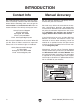
INTRODUCTION Contact Info Manual Accuracy We stand behind our machines! If you have questions or need help, contact us with the information below. Before contacting, make sure you get the serial number and manufacture date from the machine ID label. This will help us help you faster. We are proud to provide a high-quality owner’s manual with your new machine! Grizzly Technical Support 1815 W. Battlefield Springfield, MO 65807 Phone: (570) 546-9663 Email: techsupport@grizzly.
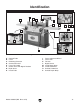
Identification B A C E D F G H I J K L O P M N Figure 1. G0495X identification. A. B. C. D. E. F. G. H. Outfeed Table Fence Rabbeting Extension Cutterhead Guard Fence Tilt Handle Control Panel with Digital Readout Depth Scale Infeed Table Model G0495X (Mfd. Since 2/19) I. J. K. L. M. N. O. P.
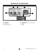
Controls & Components B C D A E F G H Figure 2. Control panel and digital readout features. A. B. C. D. -4- POWER Light STOP Button START Button Battery Compartment E. F. G. H. Digital Display ON/OFF HOLD TO CAL BUTTON Button ABS/INC MM/IN Model G0495X (Mfd.
Machine Data Sheet MACHINE DATA SHEET Customer Service #: (570) 546-9663 · To Order Call: (800) 523-4777 · Fax #: (800) 438-5901 MODEL G0495X 8" X 83" JOINTER WITH EXCLUSIVE DIGITAL HEIGHT READOUT Product Dimensions: Weight.............................................................................................................................................................. 596 lbs. Width (side-to-side) x Depth (front-to-back) x Height..................................................................
Fence Information Fence Length............................................................................................................................................. 38 in. Fence Width.......................................................................................................................................... 1-1/2 in. Fence Height......................................................................................................................................... 4-3/4 in. Fence Stops..
SECTION 1: SAFETY For Your Own Safety, Read Instruction Manual Before Operating This Machine The purpose of safety symbols is to attract your attention to possible hazardous conditions. This manual uses a series of symbols and signal words intended to convey the level of importance of the safety messages. The progression of symbols is described below. Remember that safety messages by themselves do not eliminate danger and are not a substitute for proper accident prevention measures.
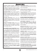
WEARING PROPER APPAREL. Do not wear clothing, apparel or jewelry that can become entangled in moving parts. Always tie back or cover long hair. Wear non-slip footwear to reduce risk of slipping and losing control or accidentally contacting cutting tool or moving parts. HAZARDOUS DUST. Dust created by machinery operations may cause cancer, birth defects, or long-term respiratory damage. Be aware of dust hazards associated with each workpiece material.
Additional Safety Instructions for Jointers Serious cuts, amputation, entanglement, or death can occur from contact with rotating cutterhead or other moving components! Flying chips from cutting operations can cause eye injuries or blindness. Workpieces or inserts/knives thrown by cutterhead (kickback) can strike nearby operator or bystanders with deadly force. To reduce the risk of serious personal injury from these hazards, operator and bystanders MUST completely heed the hazards and warnings below.
SECTION 2: POWER SUPPLY Availability Circuit Information Before installing the machine, consider the availability and proximity of the required power supply circuit. If an existing circuit does not meet the requirements for this machine, a new circuit must be installed. To minimize the risk of electrocution, fire, or equipment damage, installation work and electrical wiring must be done by an electrician or qualified service personnel in accordance with all applicable codes and standards.
Grounding Requirements This machine MUST be grounded. In the event of certain malfunctions or breakdowns, grounding reduces the risk of electric shock by providing a path of least resistance for electric current. This machine is equipped with a power cord that has an equipment-grounding wire and a grounding plug. Only insert plug into a matching receptacle (outlet) that is properly installed and grounded in accordance with all local codes and ordinances.
SECTION 3: SETUP Needed for Setup This machine presents serious injury hazards to untrained users. Read through this entire manual to become familiar with the controls and operations before starting the machine! Wear safety glasses during the entire setup process! The following items are needed, but not included, for the setup/assembly of this machine. Description Qty • Safety Glasses (for each person)................ 1 • Straightedge 4' (or longer)........................... 1 • Dust Collection System...
Inventory B C The following is a list of items shipped with your machine. Before beginning setup, lay these items out and inventory them. If any non-proprietary parts are missing (e.g. a nut or a washer), we will gladly replace them; or for the sake of expediency, replacements can be obtained at your local hardware store. NOTICE If you cannot find an item on this list, carefully check around/inside the machine and packaging materials.
Cleanup The unpainted surfaces of your machine are coated with a heavy-duty rust preventative that prevents corrosion during shipment and storage. This rust preventative works extremely well, but it will take a little time to clean. Be patient and do a thorough job cleaning your machine. The time you spend doing this now will give you a better appreciation for the proper care of your machine's unpainted surfaces.
Site Considerations Weight Load Physical Environment Refer to the Machine Data Sheet for the weight of your machine. Make sure that the surface upon which the machine is placed will bear the weight of the machine, additional equipment that may be installed on the machine, and the heaviest workpiece that will be used. Additionally, consider the weight of the operator and any dynamic loading that may occur when operating the machine.
Moving & Placing Jointer The Model G0495X is a heavy machine. Serious personal injury may occur if safe moving methods are not used. To be safe, get assistance and use power equipment to move the shipping crate and remove the machine from the crate. The Model G0495X requires the use of lifting equipment such as a forklift, engine hoist, or boom crane. DO NOT try to lift the machine by hand. To lift the jointer: 1. Unbolt the jointer from the pallet. 2.
Dust Collection DO NOT operate the Model G0495X without an adequate dust collection system. This jointer creates substantial amounts of wood dust while operating. Failure to use a dust collection system can result in short and long-term respiratory illness. Recommended CFM at Dust Port: 400 CFM Do not confuse this CFM recommendation with the rating of the dust collector.
Digital Readout Batteries —If your outfeed table is correctly set, no adjustments are necessary. —If the insert lifts the straightedge off the table or the table is below the straightedge, loosen the outfeed table lock and outfeed table positive stop bolts and jam nuts (see Figure 1, Page 3) and adjust the outfeed table height with the handwheel until the straightedge just touches a insert at its highest point of rotation.
Test Run Once assembly is complete, test run the machine to ensure it is properly connected to power and safety components are functioning correctly. If you find an unusual problem during the test run, immediately stop the machine, disconnect it from power, and fix the problem BEFORE operating the machine again. The Troubleshooting table in the SERVICE section of this manual can help. To test run the machine: 1.
5. —When operating correctly, the machine runs smoothly with little or no vibration or rubbing noises. —Investigate and correct strange or unusual noises or vibrations before operating the machine further. Always disconnect the machine from power when investigating or correcting potential problems. 6. Press the STOP button to stop the machine. 7. WITHOUT resetting the switch, press the START button. The machine should not start.
SECTION 4: OPERATIONS To reduce your risk of serious injury, read this entire manual BEFORE using machine. To reduce risk of eye injury from flying chips or lung damage from breathing dust, always wear safety glasses and a respirator when operating this machine. Basic Jointer Controls This section covers the basic controls used during routine operations. START Button: Starts motor only if the STOP button is popped out. STOP Button: Disables the START button.
Table Movement: To move the infeed or outfeed tables, loosen the table locks (see Figure 15), move the tables with the infeed or outfeed handwheels (see Figure 14), then tighten the table locks. Outfeed Handwheel Infeed Handwheel Fence Tilting: The tilt lock (see Figure 17) secures the fence at any position in the available range. The stop block locks the fence for 90° cuts. Two positive stops stop the fence at 45° inward and 45° outward for common bevel cuts.
Digital Readout ON/OFF and HOLD TO CAL: Push to turn digital readout ON and OFF. Push and hold 3–5 seconds to enter calibration mode. Push to reset display to 0.000 in incremental mode. Follow Step 2 in the previous example to reset display to 0.000 in absolute mode. To use calibration modes: MM/IN 1. Press ABS/INC button to enter absolute mode. 2. Raise or lower infeed table to desired cutting depth. 3. Press ABS/INC button to enter incremental mode. 4.
Stock Inspection & Requirements Follow these rules when choosing and jointing stock: • DO NOT joint or surface plane stock that contains large or loose knots. Injury to the operator or damage to the workpiece can occur if a knot becomes dislodged during the cutting operation. • DO NOT joint or surface plane against the grain direction. Cutting against the grain increases the likelihood of kickback, as well as tear-out on the workpiece.
Squaring Stock 2. Surface Plane on a Thickness Planer— Opposite face of workpiece is surface planed flat with a thickness planer. Squaring stock means making it flat and parallel along both length and width, and making the length and width perpendicular to one another. The purpose of squaring stock is to prepare it for accurate cuts and construction later on.
Surface Planing The purpose of surface planing (see example Figures below) on the jointer is to make one flat face on a piece of stock to prepare it for thickness planing on a planer. NOTICE If you are not experienced with a jointer, set depth of cut to 0", and practice feeding workpiece across tables as described. This will help you prepare for actual operations.
Edge Jointing Edge jointing (see example Figures below) produces a flat and true surface along the side of a workpiece by removing uneven areas. It is an essential step for squaring up warped or rough stock and when preparing a workpiece for joinery or finishing. NOTICE If you are not experienced with a jointer, set depth of cut to 0", and practice feeding workpiece across tables as described. This will help you prepare for actual operations. To edge joint on jointer: 1.
Bevel Cutting Bevel cuts (see example Figures below) can be made by setting the fence at the desired angle and feeding the workpiece firmly along the fence face, with the bottom inside corner firmly against the table. The cutting process typically requires multiple passes or cuts to bevel the entire edge of a workpiece. NOTICE If you are not experienced with a jointer, set depth of cut to 0", and practice feeding workpiece across tables as described. This will help you prepare for actual operations.
Rabbet Cutting A rabbet cut removes a portion of a workpiece edge, so it fits together with an opposing, equally sized rabbet cut on another workpiece (see example Figure below). This is a classic method of joining two workpieces that is simple, yet strong. To rabbet cut on jointer: 1. Inspect stock to ensure it is safe and suitable for the operation (see Stock Inspection & Requirements section). 2. Set infeed table height to desired cutting depth for each pass.
4. Set fence to 90° and near front of jointer, so amount of exposed cutterhead in front of fence matches size of desired rabbet. 5. Start jointer. 6. Place workpiece firmly against fence and infeed table. CAUTION: To ensure workpiece remains stable during cut, concave sides of workpiece must face toward table and fence. 7. When cutterhead guard is removed, attempting any other cut besides a rabbet directly exposes operator to moving cutterhead.
ACCESSORIES SECTION 5: ACCESSORIES Installing unapproved accessories may cause machine to malfunction, resulting in serious personal injury or machine damage. To reduce this risk, only install accessories recommended for this machine by Grizzly. NOTICE Refer to our website or latest catalog for additional recommended accessories. T20501—Face Shield Crown Protector 4" T20502—Face Shield Crown Protector 7" T20503—Face Shield Window T20451—“Kirova” Clear Safety Glasses T20452—“Kirova” Anti-Reflective S.
H2499—Small Half-Mask Respirator H3631—Medium Half-Mask Respirator H3632—Large Half-Mask Respirator H3635—Cartridge Filter Pair P100 Wood dust has been linked to nasal cancer and severe respiratory illnesses. If you work arounddust everyday, a half-mask respirator can be a lifesaver.
SECTION 6: MAINTENANCE Unpainted Cast Iron To reduce risk of shock or accidental startup, always disconnect machine from power before adjustments, maintenance, or service. Schedule For optimum performance from this machine, this maintenance schedule must be strictly followed. Ongoing To maintain a low risk of injury and proper machine operation, if you ever observe any of the items below, shut down the machine immediately and fix the problem before continuing operations: • • • • • • Loose mounting bolts.
SECTION 7: SERVICE Review the troubleshooting procedures in this section if a problem develops with your machine. If you need replacement parts or additional help with a procedure, call our Technical Support. Note: Please gather the serial number and manufacture date of your machine before calling. Troubleshooting Motor & Electrical Symptom Possible Cause Possible Solution Machine does not start or a breaker trips. 1. Emergency stop push-button is engaged/ faulty. 2. Wiring is open/has high resistance.
Motor & Electrical Symptom Possible Cause Possible Solution Machine has vibration or noisy operation. 6. Machine is incorrectly mounted or sits 6. Tighten/replace anchor studs in floor; relocate/shim machine. unevenly. 7. Replace dented fan cover; replace loose/damaged 7. Motor fan is rubbing on fan cover. fan. 8. Test by rotating shaft; rotational grinding/loose shaft 8. Motor bearings are at fault. requires bearing replacement. 9. Replace bearing(s)/re-align cutterhead. 9.
Checking/Adjusting Table Parallelism 5. Place the straightedge on the outfeed table so it hangs over the cutterhead, then lower the outfeed table until the straightedge just touches the cutterhead body, as shown in Figure 34 (rotate the cutterhead if necessary). If the tables are not parallel with the cutterhead or each other, then poor cutting results and kickback can occur. Tools Needed Qty Straightedge....................................................... 1 Wrench or Socket 12mm . ...................
Checking Infeed Table 1. Follow all the steps for checking the outfeed table parallelism to first make sure that the outfeed table is parallel with the cutterhead. 2. Raise the outfeed table higher than the cutterhead. 3. Loosen the infeed table jam nuts and positive stop bolts shown in Figure 36. Stop Bolts Jam Nut Jam Nut Figure 36. Infeed table positive stop bolts. 4.
IMPORTANT: The steps below are intended to be performed in succession with the steps involved in checking the outfeed table. Do not continue until you have followed those steps. To adjust the table parallelism: 1. 2. Place the straightedge on the outfeed table so it hangs over the cutterhead, then lower the outfeed table until the straightedge just touches the cutterhead body, as shown in Figure 34 (rotate the cutterhead if necessary). Figure 40. Front eccentric bushings.
8. 9. Place the straightedge in one of the positions shown in Figure 38, and adjust the eccentric bushings under the infeed table so the straightedge lies flat against both tables. Repeat this step with each of the remaining straightedge positions as many times as necessary until the infeed table is parallel with the outfeed table. In addition, each insert has a reference dot on one corner.
Setting Infeed Table The infeed table on the Model G0495X has positive stop bolts that, when properly set up, allow the operator to quickly adjust the infeed table between finish/final cuts and shaping/heavy cuts. Calibrating Infeed Table The depth scale on the infeed table can be calibrated or "zeroed" if it is not correct. We recommend setting the minimum depth of cut to 1⁄ 32" and the maximum depth of cut to 1⁄ 8" for most operations.
Cutterhead Guard The cutterhead guard comes pre-installed for shipping, but it may need to be adjusted if the guard does not quickly snap back against the fence when pulled out and let go. To adjust the cutterhead guard: 1. Loosen the shaft lock (see Figure 46) and remove the cutterhead guard. 2. Wind the tang on the torsion spring clockwise a quarter turn, and slide the guard shaft into the casting so the spring tang points toward the main table but does not overlap it, as shown in Figure 46. 3.
Setting Fence Stops 3. Using a 45˚ square, adjust the fence to the 45˚ inward position, as shown in Figure 48. The fence stops simplify the task of adjusting the fence to 45˚ inward, 90˚, and 45˚ outward (135˚). Tools Needed Qty 45° Square......................................................... 1 90° Square......................................................... 1 Sliding Bevel....................................................... 1 Wrench 12mm....................................................
To set the 90˚ fence stop: To set the 45˚ outward fence stop: 1. 1. Using a 90˚ square, adjust the fence to the 90˚ position, as shown in Figure 50. Figure 50. Adjusting fence to 90˚. 2. Flip the 90˚ stop block into the position shown in Figure 51. Using a sliding bevel adjusted to 135˚, adjust the fence to the 135˚ (45˚ outward) position, as shown in Figure 52. Figure 52. Adjusting fence 45˚ outward. 2. Loosen the jam nut on the 45˚ outward fence stop bolt (see Figure 53).
Adjusting/Replacing V-Belt 4. Lift the motor up, slide the V-belt off of the motor and cutterhead pulleys, and replace it with a new one. 5. Lower the motor and adjust the V-belt tension with the tension rod fasteners so there is approximately 1/2" deflection when the belt is pushed with moderate pressure, as shown in Figure 55. V-belt removal and replacement involves removing the V-belt, rolling it off of the pulleys, replacing it with a new belt, then retensioning it. To adjust/replace the V-belt: 1.
Pulley Alignment Cutterhead Pulley Pulley alignment is another important factor in power transmission and belt life. The pulleys should be parallel to each other and in the same plane (coplaner) for optimum performance. Alignment Each pulley can be adjusted by loosening the motor mount fasteners, sliding the motor in or out, and retightening the fasteners to lock the motor pulley in place. Motor Pulley Tools Needed: Qty Wrench or Socket 17mm.................................... 1 Figure 57.
machine SECTION 8: WIRING These pages are current at the time of printing. However, in the spirit of improvement, we may make changes to the electrical systems of future machines. Compare the manufacture date of your machine to the one stated in this manual, and study this section carefully. If there are differences between your machine and what is shown in this section, call Technical Support at (570) 546-9663 for assistance BEFORE making any changes to the wiring on your machine.
Electrical Components Figure 60. Capacitor wiring. Figure 59. Magnetic switch wiring. Model G0495X (Mfd.
Wiring Diagram Ground Hot CONTROL PANEL (viewed from behind) G Ground X1 230 VAC Hot 22 X2 POWER 13 21 14 6-20 Plug 14 START STOP 13 21 22 DIGITAL READOUT (2 AAA Batteries) SENSOR 1 1.5V, 357/303 Battery A L1/1 L2/3 L3/5 NO13 NC 21 T1/2 MAGNETIC SWITCH T2/4 T3/6 See Figure 59 NO14 B RESET RA-20 AMP 1/2 3/4 5/6 The motor wiring shown here is current at the time of printing, but it may not match your machine. Always use the wiring diagram inside the motor junction box.
SECTION 9: PARTS We do our best to stock replacement parts when possible, but we cannot guarantee that all parts shown are available for purchase. Call (800) 523-4777 or visit www.grizzly.com/parts to check for availability.
Base Breakdown Base 168V2-9 168V2-6 168V2-10 168V2-8 168V2 168V2-11 168V2-7 168V2-13 168V2-6 168V2-14 168V2-5 168V2-15 168V2-12 168V2-16 168V2-4 B 168V2-3 168V2-18 80 166 168V2-17 53 168V2-19 81 78 81 168V2-2 168V2-20 88 8 4 89 174 168V2-21 165 26 164 169 B 90 87 79 91 167 82 168V2-1 77 26 94 83 173 174 9 164 172 89 94 98V2 88 3 91 90 171 140 26 169 93 170 96 95 167 92 94 94 174 145 89 140 A 164 100 90 26 87 154 144 100 174 154 158 A 89 92 93 100 164 4 90 154 81 96 173 95 172 166 83 94 140 82 93 165 91 92
Base Parts List REF PART # DESCRIPTION REF PART # DESCRIPTION 4 26 77 78 79 81 82 83 87 88 89 90 91 92 93 94 95 96 98V2 100 140 144 145 154 158 164 165 166 167 ROLL PIN 4 X 25 HEX NUT 5/16-18 KNOB GUARD COVER DOUBLE-END STUD BALL BEARING 6000ZZ PINION GEAR SHAFT HEX BOLT 5/16-18 X 1-3/4 HEX BOLT 5/16-18 X 1 HEX BOLT 3/8-16 X 2 FLAT WASHER 10MM LIFTING ROD KNOB M4-.7, D46, 7-LOBE HANDWHEEL ASSEMBLY BALL BEARING 6002ZZ KEY 5 X 5 X 10 SPIRAL GEAR SHAFT BASE V2.02.
Table 47 65 70V2 68 64V2 46 63 44 68 66 63 181 175 176 177 178 184 179 180 76 47 43 44 44 45-7 45-6 45-8 45-9 127 186V2 9 68 66 48 65 215 76 43 44 67 45-5 45-10 45-1 45-2 45-3 45-4 49 50 51 52 55 45 133 53 54 48 56 57 58V2 63 76 47 9 72V3 84V2 43 44 44 44 44 68 63 66 67 65 215 65 68 71V2 64V2 68 66 61V2 REF PART # DESCRIPTION REF PART # DESCRIPTION 9 43 44 45 45-1 45-2 45-3 45-4 45-5 45-6 45-7 45-8 45-9 45-10 46 47 48 49 50 51 52 53 54 55 56 57 CAP SCREW 1/4-20 X 3/8 SE
Stand 102V2-1 102V2-4 102V2-8 102V2-2 102V2-5 102V2-9 102V2-3 102V2-6 102V2-10 102V2-7 102V2-11 101 102V2-14 102V2-13 102V2 104 21 21 104 105 106 107 25 103 2 102V2-12 102V2-15 26 107 103 110 109 116 149V3 2 117 108 119V2 152 151 150 141V3 147V3 115 142V3 153 120 100 118 100 99 121 122 99 8 189 111 147-1 125-1 125-4 125-2 125-3 125-5 8 148V2 124 114 129 193 194 113 125-6V2 192 191 195 125 112 90 182 182 60 146 128V2 125-7 86 85 Model G0495X (Mfd.
Stand Parts List REF PART # DESCRIPTION REF PART # DESCRIPTION 2 8 21 25 26 60 85 86 90 99 100 101 102V2 102V2-1 102V2-2 102V2-3 102V2-4 102V2-5 102V2-6 102V2-7 102V2-8 102V2-9 102V2-10 102V2-11 102V2-12 102V2-13 102V2-14 102V2-15 103 104 105 106 107 108 109 110 111 112 113 P0495X002 P0495X008 P0495X021 P0495X025 P0495X026 P0495X060 P0495X085 P0495X086 P0495X090 P0495X099 P0495X100 P0495X101 P0495X102V2 P0495X102V2-1 P0495X102V2-2 P0495X102V2-3 P0495X102V2-4 P0495X102V2-5 P0495X102V2-6 P0495X102V2-7
Labels & Cosmetics 201 202 200V2 217 216 203 212 211 206 204 210 205 209 208 207 REF PART # DESCRIPTION REF PART # DESCRIPTION 200V2 201 202 203 204 205 206 207 P0495X200V2 P0495X201 P0495X202 P0495X203 P0495X204 P0495X205 P0495X206 P0495X207 MACHINE ID LABEL V2.02.
WARRANTY & RETURNS Grizzly Industrial, Inc. warrants every product it sells for a period of 1 year to the original purchaser from the date of purchase. This warranty does not apply to defects due directly or indirectly to misuse, abuse, negligence, accidents, repairs or alterations or lack of maintenance.