
Full Product Manual


G0513 Series Bandsaws (Mfd. Since 07/18)
-67-
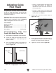
Checking/Adjusting Guide Post
Parallel with Blade Front-to-Back
1. DISCONNECT BANDSAW FROM POWER!
2. Loosen the guide post lock knob, lower the
blade guide assembly to within 1" of the table
top, then tighten the lock knob.
3. Remove the screws that secure the guide
post guard and move it up and out of the
way.
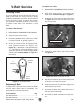
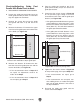
4. Measure the distance "A" between the upper
front face of the guide post rack and the back
of the blade (see Figure 99).
Distance "A"
Distance "B"
(Right Side View)
Guide Post
Blade
Figure 99. Example of measuring distance
between rack and blade at top of guide post.
5. Measure the distance "B" between the bot-
tom front face of the guide post rack and the
back of the blade (see Figure 99).
—If the measurements taken in Steps 4–5
are equal, no adjustments need to be
made. Go to Step 9.
—If the measurements taken in Steps 4–5
are not equal, go to Step 6.
6. Place the guide post guard on top of the
guide post assembly so you can access the
guide post bracket.
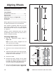
7. Loosen the four screws shown in Figure 98
on the previous page enough to fit metal
shims between the frame and the guide post
bracket (see Figure 100).
—If the guide post to blade distance is greater
at the bottom than at the top, place a shim
between the bottom of the bracket and the
frame (Shim "A"). This will tilt the bottom of
the guide post toward the blade.
—If the guide post to blade distance is less
at the bottom than at the top, place a shim
between the top of the bracket and the
frame (Shim "B"). This will tilt the bottom of
the guide post away from the blade.
Shim "B"
(Left Side View)
Shim "A"
Frame
Blade
Guide
Post
Guide
Bracket
Figure 100. Location for placing shims.
8. Tighten the four screws shown in Figure 98
on the previous page, then repeat Steps 4–5.
—If the measurements are equal, go to
Step 9.
—If the measurements are not equal, con-
tinue adding shims as needed until guide
post rack to blade distance is the same at
the top and bottom.
9. Re-install the guide post guard with the
screws removed in Step 3.