
Use and Care Manual

G0555LX (Mfg. Since 3/13)
-21-
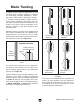
— If the blade rides in the center of the upper
wheel and is centered on the peak of the
wheel crown, it is properly tracking and you
are done with this procedure—proceed to
Dust Collection on Page 22.
— If the blade does is not properly tracking,
then continue with this procedure to adjust
it.
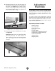
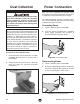
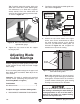
7. Loosen the wing nut on the tracking knob
(see Figure 24).
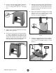
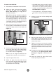
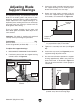
3. Move the blade tension quick release lever all
the way right (as viewed from the rear of the
machine) to apply tension to the blade (see
Figure 23).
4. Use the tension knob on top of the bandsaw
to bring the upper edge of the indicator block
to the appropriate blade tension scale mark
for the blade width (see Figure 23).
Note: If you are using the blade that was
shipped with the machine, this would be
3
⁄8".
5. Open the upper wheel cover.
6. Rotate the upper wheel by hand several
times and watch how the blade rides on the
wheel crown (see Figure 21 on Page 19 for
an illustration of this concept).
8. Spin the upper wheel with one hand and
slowly adjust the tracking knob with the other
hand until the blade consistently tracks in the
center of the wheel.
9. Tighten the wing nut to secure the setting,
then spin the upper wheel several times to
confirm the tracking. If necessary, repeat the
adjustment procedure until the blade is track-
ing properly.
10. Re-adjust the blade guide bearings toward
the blade (refer to Adjusting Blade Guide
Bearings on Page 26 for detailed instruc-
tions).
11. Close and secure the upper wheel cover
before operating the bandsaw.
Figure 24. Tracking knob and wing nut.
Tracking
Knob
Wing Nut
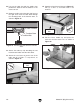
To center track the blade:
1. DISCONNECT BANDSAW FROM POWER!
2. Adjust the upper and lower blade guides
away from the blade (refer to Adjusting
Blade Guide Bearings on Page 26 for
detailed instructions).
Note: When adjusting the blade tracking for
the test run in this procedure, the blade must
have a reasonable amount of tension to sim-
ulate operating conditions. After the test run
is successfully completed, you will perform
a thorough version of the following steps to
more accurately tension the blade.
Figure 23. Example of tension applied for a
3
⁄8"
blade.
Quick Release
Lever
Tensioned for
a
3
⁄8" Blade