
Use and Care Manual

G0555LX (Mfg. Since 3/13)
-27-
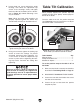
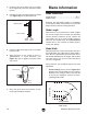
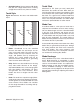
4. Loosen both cap screws behind the guide
bearings, then rotate the adjustment cap
screws so the bearings evenly and lightly
touch the sides of the blade (see the illustra-
tion in Figure 35) without deflecting it one
way or the other.
Note: When the blade guide bearings are
properly adjusted against the blade, they
should rotate smoothly as the blade moves.
Figure 35. Blade guide bearings evenly and
lightly touching the sides of the blade.
5. Using a hex wrench, tighten the locking cap
screws to secure the settings. To prevent
unwanted movement while tightening, use
a hex wrench to hold the adjustment cap
screws in place while re-tightening the lock-
ing cap screws. Re-check the setting after
tightening.
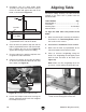
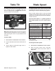
Table Tilt Calibration
When properly adjusted, the positive stop bolt
enables the table to be quickly returned perpen-
dicular to the blade.
To tilt the table to the left, the positive stop bolt
(see Figure 36) must be lowered, then re-adjust-
ed after the table is returned to 0°.
Tools Needed Qty
Wrench 13mm ................................................... 1
Phillips Screwdriver #2 ...................................... 1
Machinist's Square ............................................ 1
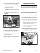
To set the positive stop so the table is 90˚ to
the blade:
1. Make sure the blade is correctly tensioned as
described in Tensioning Blade on Page 23.
2. DISCONNECT BANDSAW FROM POWER!
3. Loosen the two table lock knobs that secure
the table to the trunnions.
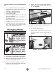
4. Loosen the jam nut that locks the positive
stop bolt in place.
Figure 36. Positive stop bolt set so table is 90°
to the blade (viewed from behind the table).
Positive
Stop Bolt
Jam Nut
Whenever changing a blade or adjusting the
blade tension or tracking, the support and
guide bearings must be re-adjusted before
resuming operation to ensure proper blade
support.