MODEL G0442/G0601 5 HP CYCLONE DUST COLLECTOR OWNER'S MANUAL (For models manufactured since 03/12) COPYRIGHT © APRIL, 2010 BY GRIZZLY INDUSTRIAL, INC., REVISED DECEMBER, 2018 (JL) WARNING: NO PORTION OF THIS MANUAL MAY BE REPRODUCED IN ANY SHAPE OR FORM WITHOUT THE WRITTEN APPROVAL OF GRIZZLY INDUSTRIAL, INC. #TS12622 PRINTED IN TAIWAN V3.12.
This manual provides critical safety instructions on the proper setup, operation, maintenance, and service of this machine/tool. Save this document, refer to it often, and use it to instruct other operators. Failure to read, understand and follow the instructions in this manual may result in fire or serious personal injury—including amputation, electrocution, or death. The owner of this machine/tool is solely responsible for its safe use.
Table of Contents INTRODUCTION................................................ 2 Manual Accuracy............................................ 2 Contact Info.................................................... 2 Machine Description....................................... 2 Identification.................................................... 3 G0442 Machine Data Sheet........................... 4 G0601 Machine Data Sheet........................... 6 SECTION 1: SAFETY........................................
INTRODUCTION Manual Accuracy Contact Info We are proud to provide a high-quality owner’s manual with your new machine! We stand behind our machines! If you have questions or need help, contact us with the information below. Before contacting, make sure you get the serial number and manufacture date from the machine ID label. This will help us help you faster. We made every effort to be exact with the instructions, specifications, drawings, and photographs in this manual.
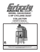
Identification Motor Outlet Hose Blower Assembly Noise Muffler Inlet Port Cyclone Assembly Canister Filter Assembly Junction Box Control Box Canister Collection Bag Collection Drum w/Casters Vacuum Hose Figure 1. Identification (Model G0442 shown). To reduce the risk of serious injury when using this machine, read and understand this entire manual before beginning any operations.
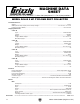
G0442 Machine Data Sheet MACHINE DATA SHEET Customer Service #: (570) 546-9663 · To Order Call: (800) 523-4777 · Fax #: (800) 438-5901 MODEL G0442 5 HP CYCLONE DUST COLLECTOR Product Dimensions: Weight.............................................................................................................................................................. 517 lbs. Width (side-to-side) x Depth (front-to-back) x Height............................................................. 63 x 56-7/8 x 111-1/2 in.
Main Specifications: Operation Dust Collector Type.......................................................................................................... Two-Stage (Cyclone) Approved Dust Types................................................................................................................................ Wood Filter Type............................................................................................................................... Pleated Cartridge Airflow Performance......
G0601 Machine Data Sheet MACHINE DATA SHEET Customer Service #: (570) 546-9663 · To Order Call: (800) 523-4777 · Fax #: (800) 438-5901 MODEL G0601 5 HP 3‐PHASE CYCLONE DUST COLLECTOR Product Dimensions: Weight.............................................................................................................................................................. 517 lbs. Width (side-to-side) x Depth (front-to-back) x Height.............................................................
Motors: Main Horsepower................................................................................................................................................ 5 HP Phase.................................................................................................................................................... 3-Phase Amps................................................................................................................................................. 13.7A/6.9A Speed...........
SECTION 1: SAFETY For Your Own Safety, Read Instruction Manual Before Operating This Machine The purpose of safety symbols is to attract your attention to possible hazardous conditions. This manual uses a series of symbols and signal words intended to convey the level of importance of the safety messages. The progression of symbols is described below. Remember that safety messages by themselves do not eliminate danger and are not a substitute for proper accident prevention measures.
WEARING PROPER APPAREL. Do not wear clothing, apparel or jewelry that can become entangled in moving parts. Always tie back or cover long hair. Wear non-slip footwear to reduce risk of slipping and losing control or accidentally contacting cutting tool or moving parts. HAZARDOUS DUST. Dust created by machinery operations may cause cancer, birth defects, or long-term respiratory damage. Be aware of dust hazards associated with each workpiece material.
Additional Safety for Dust Collectors INTENDED USE. This dust collector is only intendedforcollectingwooddustandchipsfrom woodworking machines. DO NOT use this dust collector to collect metal, dirt, pebbles, drywall, asbestos, lead paint, silica, liquids, aerosols, or anyflammable,combustible,orhazardousmaterials. hazarDoUS DUST. Dust created while using machinery may cause cancer, birth defects, or long-term respiratory damage.
SECTION 2: POWER SUPPLY Availability Circuit Requirements Before installing the machine, consider the availability and proximity of the required power supply circuit. If an existing circuit does not meet the requirements for this machine, a new circuit must be installed. To minimize the risk of electrocution, fire, or equipment damage, installation work and electrical wiring must be done by an electrician or qualified service personnel in accordance with all applicable codes and standards.
G0601 Circuit Requirements for 220V The Model G0601 is prewired to operate on a 220V power supply circuit that has a verified ground and meets the following requirements: Nominal Voltage.........................................220V Cycle...........................................................60 Hz Phase..................................................... 3-Phase Circuit Rating.................. Time Delay 30 Amps Connection.......
G0601 440V Conversion The Model G0601 can be converted for 440V operation. This conversion job consists of disconnecting the machine from the power source, replacing the control box assembly and the motor cord, and rewiring the motor for 440V operation. All wiring changes must be inspected by a qualified electrician before the machine is connected to the power source. If you need help at any time during this procedure, call Grizzly Tech Support at (570) 546-9663.
Correcting Phase Polarity (G0601 Only) This subsection is only provided for troubleshooting. If you discover during the test run that the machine will not operate, or that the impeller spins backward, the power connections may be wired out-of-phase. Without the proper test equipment to determine the polarity of the power source legs, wiring machinery to 3-phase power may require trial-and-error.
SECTION 3: SETUP Needed for Setup This machine presents serious injury hazards to untrained users. Read through this entire manual to become familiar with the controls and operations before starting the machine! Wear safety glasses during the entire setup process! This machine and its components are very heavy. Get lifting help or use power lifting equipment such as a forklift to move heavy items. The following are needed to complete the setup process, but are not included with the machine.
Inventory The following is a description of the main components shipped with the machine. Lay the components out to inventory them. Collector Box Contents (Figure 5): Qty A. Intake Cylinder............................................ 1 B. Cyclone Funnel........................................... 1 C. Intake Barrel................................................ 1 D. Collection Bags — Canister Filter........................................ 2 — Collection Drum.................................... 2 E.
Stand Box Contents (Figure 6): Qty A. Lower Stand Legs....................................... 4 B. Upper Stand Legs....................................... 4 C. Upper Stand Braces.................................... 4 D. Lower Stand Braces.................................... 4 E. Collector Mounting Brackets....................... 4 F. Hardware Bags —Hex Bolts 3⁄8"-16 x 3⁄4"............................. 64 —Lock Nuts 3⁄8"-16..................................... 64 —Flat Washers 3⁄8"...........................
Site Considerations Weight Load Physical Environment Refer to the Machine Data Sheet for the weight of your machine. Make sure that the surface upon which the machine is placed will bear the weight of the machine, additional equipment that may be installed on the machine, and the heaviest workpiece that will be used. Additionally, consider the weight of the operator and any dynamic loading that may occur when operating the machine.
Mounting to Shop Floor Since your dust collector will be hardwired to the power source, we strongly recommend securing your machine to the floor. Consult with your electrician to ensure compliance with applicable codes. Because floor materials may vary, floor mounting hardware is not included. Bolting to Concrete Floors Lag shield anchors with lag bolts and anchor studs (Figure 9) are two popular methods for anchoring an object to a concrete floor.
Assembly 2. Note: Do not fully tighten the fasteners for now. The Model G0442/G0601 is a heavy machine. Serious personal injury may occur if safe moving methods are not used. To be safe, get assistance and use power equipment to move the shipping crate and remove the machine from the crate. x 16 To assemble the dust collector: 1. Connect the upper stand legs with the lower stand braces, using (16) 3⁄8"-16 x 3⁄4" hex bolts, (32) 3⁄8" flat washers, and (16) 3⁄8"-16 lock nuts (see Figure 10).
4. Attach the cyclone funnel to the intake barrel with a barrel gasket between them, as shown in Figure 13, with (12) 5⁄16"-18 x 1" hex bolts, (24) 5⁄16" flat washers, and (12) 5⁄16"-18 hex nuts. 6. Place a large piece of cardboard on the ground to prevent scraping the parts on the bare floor during the next steps. 7. With the help of another person, lay the stand assembly on its side on the cardboard and slide the collector assembly into the stand assembly, as shown in Figure 15.
10. Lift the assembly upright and rotate it so the inlet/outlet directions are suitable for your shop. 11. Lift the motor/blower housing assembly with a forklift and attach the intake cylinder to the bottom of the housing, as shown Figure 17, using (4) 5⁄16"-18 x 3⁄4" hex bolts and (4) 5⁄16" flat washers.
14. Attach the assembly to the intake barrel, as shown in Figure 20, with (12) 5⁄16"-18 x 3⁄4" hex bolts and (12) 5⁄16" flat washers. 16. Attach one roll of 3 x 15 x 700mm foam tape to the outside lip of each outlet port, as shown in Figure 21. 17. Attach the two filter cross braces to the L-braces, as shown in Figure 22, using (4) 3 ⁄8"-16 x 3⁄4" hex bolts, (8) 3⁄8" flat washers, and (4) 3⁄8"-16 hex nuts. x4 x 12 Figure 20. Securing blower on intake barrel. 15.
19. Using the forklift, lift the entire assembly approximately 2" off the ground to gain clearance for filter installation. 20. Mount the two filters to the braces with brace gaskets between them, as shown in Figure 24, using (8) 5⁄16"-18 x 3⁄4" hex bolts and (8) 5⁄16" fender washers. 22. Using the forklift, raise the assembly up and attach the lower stand legs to the upper stand legs, as shown in Figure 26, using (24) 3⁄8"-16 x 3⁄4" hex bolts, (48) 3⁄8" flat washers, and (24) 3 ⁄8"-16 lock nuts.
24. Connect the upper and lower collection drums together with the included metal clamp and the provided hex bolt and nut, as shown in Figure 28. 26. Install the three drum latches, as shown in Figure 30, with the (6) 10-24 x 3⁄8" Phillips head screws and (6) 10-24 hex nuts included in the box with the drum latches. Use the remaining (6) 10-24 x 3⁄8" Phillips head screws and (6) 10-24 hex nuts to plug the lower latch mounting holes.
. Install the larger plastic collection bag into the drum, place the lid on it and hook the latch over the lid, as shown in Figure 32, then clamp it in place. 30. Fit the plastic collection bags over the bottom of the filters and clamp them in place with the metal bag clamps, as shown in Figure 34. Bag Clamp Figure 34. Canister filter collection bag installed. Figure 32. Latch hooked over the lid for clamping. 29.
32. Slide the reducer over the inlet port on the barrel (Figure 36), line up the mounting holes, and secure it in place with the (3) M4 x 12 sheet metal screws. 34. Mount the switch on the stand, as shown in Figure 38, with (3) 3⁄8"-16 x 3⁄4" hex bolts, (6) 3 ⁄8" flat washers, and (3) 3⁄8"-16 hex nuts. Reducer x3 Figure 36. Reducer installed. 33. Secure the vacuum hose inside the upper and lower stand legs with the (2) U-shaped clips (see Figure 37). Figure 38. Switch mounted to stand.
Due to the complexity required for planning, bending, and installing the conduit necessary for a code-compliant hardwire setup, an electrician or other qualified person MUST perform this type of installation. Hardwire setups typically require power supply wires to be enclosed inside of a solid or flexible conduit, which is securely mounted at both ends with the appropriate conduit fittings. All work must adhere to the required electrical codes.
Test Run 7. Press the TIMER button on the control box and cycle through each of the times to make sure the indicators light. When the assembly is complete, test run the dust collection system to make sure it operates properly. 8. Press the TIMER button on the remote control and cycle through the times in the same manner as Step 7.
SECTION 4: DESIGNING THE SYSTEM General Always guard against static electrical build up by grounding all dust collection lines. The Model G0442/G0601 is designed to be a central dust collector system. The large suction capacity of the Model G0442/G0601 allows great flexibility in planning and designing of the dust collection duct layout. Duct Material You have many choices regarding main line and branch line duct material.
Metal Duct Flexible Duct Advantages of metal duct is its conductivity and that it does not contribute to static electrical charge build-up. However, static charges are still produced when dust particles strike other dust particles as they move through the duct. Since metal duct is a conductor, it can be grounded quite easily to dissipate any static electrical charges. Flexible hose is generally used for short runs, small shops and at rigid duct-to-tool connections.
System Design Decide Who Will Design For most small-to-medium sized shops, you can design and build the dust collection system yourself without hiring engineers or consultants. We have included some basic information here to get you started on a basic design. If you have a large shop or plan to design a complicated system, we recommend doing additional research beyond this manual or seeking the help of an expert.
3. Directional changes should be kept to a minimum. The more directional change fittings you use directly increases the overall resistance to airflow. 4. Gradual directional changes are more efficient than sudden directional changes (i.e. use the largest corner radius possible when changing hose or pipe direction). 5. Each individual branch line should have a blast gate immediately after the branch to control suction from one machine to another. 6.
Determining Main Line Duct Size The general rule of thumb for a main line duct is that the velocity of the airflow must not fall below 3500 FPM. For small/medium sized shops, using the inlet size of the dust collector as the main line duct size will usually keep the air velocity above 3500 FPM and, depending on your system, will allow you to keep multiple branches open at one time. Mark your drawing, as shown in the figure below, but using the inlet size for your dust collector as the main line.
Planning Drop Downs Duct Dia. Approximate Static Pressure Loss Per Foot of Rigid Pipe Approximate Static Pressure Loss Per Foot of Flex Pipe Main Lines at 3500 FPM Branch Lines at 4000 FPM Main Branch Lines Lines at 3500 at 4000 FPM FPM 2" 0.091 0.122 0.35 0.453 2.5" 0.08 0.107 0.306 0.397 3" 0.071 0.094 0.271 0.352 4" 0.057 0.075 0.215 0.28 5" 0.046 0.059 0.172 0.225 6" 0.037 0.047 0.136 0.18 To Planer 7" 0.029 0.036 0.106 0.141 Figure 54. Drop down setup. 8" 0.
3. Add the additional factors from the following table to your list. Additional Factors Seasoned (well used) Dust Collection Filter Entry Loss at Large Machine Hood 5. Compare the total static pressure loss for that line to the closest CFM given in Figure 58. Example: The G0442/G0601 Data Sheet Performance Curve is illustrated in Figure 58. Find 4.
— If the CFM for your static pressure loss is below the requirement of the machine, then that line will not effectively collect the dust. You must then modify some of the factors in that line to reduce the static pressure loss. Some of the ways to do this include 1) installing larger duct, 2) reducing amount of flexible duct used, 3) increasing machine dust port size, 4) moving machine closer to dust collector to eliminate duct length, and 5) reducing 90˚ elbows or replacing them with 45˚ elbows.
System Grounding Since plastic hose is abundant, relatively inexpensive, easily assembled and air tight, it is a very popular material for conveying dust from woodworking machines to the dust collector. We recommend using flexible hose (flex-hose) to connect the woodworking machine to the dust collector. However, plastic flex-hose and plastic duct are an insulator, and dust particles moving against the walls of the plastic duct create a static electrical build up.
SECTION 5: OPERATIONS Damage to your eyes, lungs, and ears could result from using this machine without proper protective gear. Always wear safety glasses, a respirator, and hearing protection when operating this machine. NOTICE If you have never used this type of machine or equipment before, WE STRONGLY RECOMMEND that you read books, trade magazines, or get formal training before beginning any projects.
Control Box Panel Use the illustration of the control box panel in Figure 62 and the descriptions that follow to become familiar with the functions of the buttons on the control box. A. Timer Indicator Lights: Turns ON when a timer setting is selected. B. Infrared Port: Receives infrared communication from the remote control. C. ON/OFF Button: Starts/stops the dust collector motor. D. Timer Button: Cycles through the available timer settings.
ACCESSORIES SECTION 6: ACCESSORIES H5293—4" Metal Duct Starter Kit H5295—5" Metal Duct Starter Kit H5297—6" Metal Duct Starter Kit Save over 20% with this great starter kit. Includes: (2) machine adapters, (10) pipe clamps, (3) 5' straight pipes, (1) branch, (3) pipe hangers, (1) end cap, (3) adjustable nipples, (1) 90˚ elbow, and (1) 60˚ elbow. Figure 63. Metal Duct Starter Kit.
Metal Elbows These industrial metal elbows are available from 4"–8" with 90˚, 60˚, 45˚, or 30˚ curves. Also, available with a 90˚ long radius curve. Call (800) 523-4777 or visit www.grizzly. com for more information and pricing. 90° Metal Branches We carry many different branches, all designed to minimize airflow resistance. 90° Long Radius Figure 69. Metal Branches. 30° 45° 60° Reducers & Adapters We carry a multitude of reducers and elbows to cover most applications from 4" through 9". Figure 67.
SECTION 7: MAINTENANCE Cleaning Filters Always disconnect power to the machine before performing maintenance. Failure to do this may result in serious personal injury. Schedule For optimum performance from your machine, check the following items during operation. If you notice a problem, resolve it before continuing operation. At the end of the day, make sure the machine is turned OFF and disconnected from power. During Operations: • Dust collection drums and bags. • Check/repair loose mounting bolts.
Rinsing Filter 3. For a thorough cleaning, the filter can be removed and rinsed off. However, make sure to clean the filter with the brush system first. Allow the filter to air dry. Do not use compressed air on the pleated filter or leave it in the sun to dry—this could damage it. Pull the black handle all the way down and secure the cable into the handle hook at the bottom of the canister assembly, as shown in Figure 73, to hold it in place during the following steps.
6. With help from another person to steady the canister assembly, turn it upside down and remove the two hex bolts, hex nuts, and flat washers from the cross support (see Figure 75), then remove the canister base from the assembly. 8. Before re-inserting the filter into the assembly, make sure that the filter brush base is aligned with two of the fastener holes around the base of the assembly (see Figure 77). This will allow the canister base to align with the fastener holes around the brush base.
SECTION 8: SERVICE Review the troubleshooting and procedures in this section to fix or adjust the machine if a problem develops. If you need replacement parts or you are unsure of your repair skills, then feel free to call our Technical Support at (570) 546-9663. Troubleshooting Symptom Possible Cause Possible Solution Machine does not start or a breaker trips. 1. Wall fuse/circuit breaker is blown/tripped. 1. Ensure circuit size is suitable for this machine; replace weak breaker. 2.
Symptom Possible Cause Possible Solution Loud, repetitious noise, or excessive vibration coming from dust collector. 1. Dust collector is not on a flat surface and wobbles. 2. Impeller is loose or damaged and unbalanced. 1. Stabilize the dust collector. 3. The motor mounting or housing connections are loose. 4. Impeller is loose on the motor shaft. 5. Motor fan cover is dented, causing the motor fan to hit the cover while spinning.
SECTION 9: WIRING These pages are current at the time of printing. However, in the spirit of improvement, we may make changes to the electrical systems of future machines. Study this section carefully. If there are differences between your machine and what is shown in this section, call Technical Support at (570) 546-9663 for assistance BEFORE making any changes to the wiring on your machine. Wiring Safety Instructions SHOCK HAZARD.
g0442 wiring G0442 Wiring Diagram Ground 1-PHASE 220 VAC Hot DISCONNECT SWITCH (as recommended) Run Capacitor 40µF 450VAC Hot Start Capacitor 400MFD 250VAC 220V Motor OL_NO AC OUT AC IN A1 1L1 3L2 5L3 A2 13NO NHD C-18D Ground Circuit Board 2T1 4T2 6T3 14NO A2 21 25 22 O 23 98 97 96 R 95 NTH-25 2T1 4T2 ON/OFF Switch 6T3 220V Magnetic Contactor Switch and Overload Relay Run Capacitor Start Capacitor CONNECTION CW D.E. 5 6 1 2 ~ Figure 78. Model G0442 motor wiring.
g0601 wiring G0601 220V Wiring Diagram 220V Motor Ground 3-PHASE 220 VAC Hot Hot DISCONNECT SWITCH (as recommended) Hot OL_NO AC IN A1 1L1 3L2 5L3 A2 13NO NHD C-18D Ground Circuit Board 2T1 4T2 6T3 14NO A2 SE SOURCE 10 11 13 O 98 15 97 96 R 95 ON/OFF Switch NTH-1 5 GROUND 2T1 O13 O14 95 AC OUT 6T3 220V Magnetic Contactor Switch and Overload Relay ON A2 4T2 Magnetic Switch OFF AC2 AC1 COM S IC(220V) Circuit Board 4 5 6 4 5 6 7 8 9 7 8 9 1 2 3 1
Ground Hot Hot 440V Magnetic Contactor Switch and Overload Relay OL_NO A2 AC OUT AC IN Ground A1 1L1 3L2 5L3 13NO NHD C-09D Circuit Board 2T1 30VA Transformer 4T2 6T3 14NO A2 0 440 460 0 220 230 E O 98 8 97 NTH-8 2T1 4T2 6T3 96 R 95 ON/OFF Switch ON OFF COM S 220V) ircuit Board g 3-PHASE 440 VAC DISCONNECT SWITCH (as recommended) Hot 6 AC1 G0601 440V Wiring Diagram 4 5 6 4 5 6 7 8 9 7 8 9 1 2 3 1 2 3 HIGH VOLTAGE 440V 440V Motor LOW VOLTAGE 220V Mo
Parts Breakdown SECTION 10: PARTS Main G0442 1-1 1-2 1-7 1 1-4 1-6 1-9 1-10 1-8 8 6 7 2 17 14 15 18 16 4 G0601 1-1 1-3 1-4 3V2-1 90 126 91 3V2-2 74 75 70 3V2-3 92 Connections: OUTPUT HZ VOLT AMP RPM PHASE DUTY HEAT WEIGHT CLASS DATE SER. NO.
G0442 Only Parts List REF PART # DESCRIPTION REF PART # DESCRIPTION 1 1-1 1-2 1-4 1-5 1-6 1-7 1-8 1-9 1-10 2 MOTOR 5HP 220V 1-PH MOTOR FAN COVER MOTOR FAN S CAPACITOR 400M 250V 1-3/4 X 3-3/4 R CAPACITOR 40M 450V JUNCTION BOX BALL BEARING 6207ZZ BALL BEARING 6205ZZ CONTACT PLATE CENTRIFUGAL SWITCH 3450 RPM MOTOR CORD 12G 3W 3V2 3V2-1 3V2-2 3V2-3 3V2-4 99V2 100V2 101 125 126 P0442003V2 P0442003V2-1 P0442003V2-2 P0442003V2-3 P0442003V2-4 P0442099V2 P0442100V2 P0442101 P0442125 P0442126 CONT BOX ASSY 2
G0442/G0601 Common Parts List REF PART # DESCRIPTION REF PART # DESCRIPTION 34 35 36AV2 36V2 36-1V2 36-4V2 37V2 38V2 39 40 41 42 43 44 45 46 47V2 48 49 50 51 52 53 54 54-1 54-2 55V2 56 57AV2 57V2 58 59 60 61 62 63 64 65 66 67 68 69 70 71 72 73 P0442034 P0442035 P0442036AV2 P0442036V2 P0442036-1V2 P0442036-4V2 P0442037V2 P0442038V2 P0442039 P0442040 P0442041 P0442042 P0442043 P0442044 P0442045 P0442046 P0442047V2 P0442048 P0442049 P0442050 P0442051 P0442052 P0442053 P0442054 P0442054-1 P0442054-2 P0442
WARRANTY CARD Name _____________________________________________________________________________ Street _____________________________________________________________________________ City _______________________ State _________________________ Zip _____________________ Phone # ____________________ Email _________________________________________________ Model # ____________________ Order # _______________________ Serial # __________________ The following information is given on a voluntary basis.
FOLD ALONG DOTTED LINE Place Stamp Here GRIZZLY INDUSTRIAL, INC. P.O.
WARRANTY AND RETURNS WARRANTY AND RETURNS Grizzly Industrial, Inc. warrants every product it sells for a period of 1 year to the original purchaser from the date of purchase. This warranty does not apply to defects due directly or indirectly to misuse, abuse, negligence, accidents, repairs or alterations or lack of maintenance.