
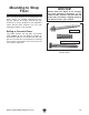
Use and Care Manual


-28-
Model G0442/G0601 (Mfg Since 3/12)
Power Connection
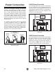
Due to the complexity required for planning,
bending, and installing the conduit necessary
for a code-compliant hardwire setup, an electri-
cian or other qualified person MUST perform
this type of installation. Hardwire setups typically
require power supply wires to be enclosed inside
of a solid or flexible conduit, which is securely
mounted at both ends with the appropriate con-
duit fittings. All work must adhere to the required
electrical codes.
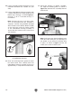
The hardwire setup for this machine must include
a locking disconnect switch (see Figure 39)
between the power source and the machine. This
switch serves as the means to completely discon-
nect the machine from power to prevent elec-
trocution accidental startup during adjustments,
maintenance, or service to the machine.
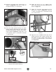
G0442 Power Connection
The incoming power wires must be connected to
the two terminals on the contactor marked 1L1
and 5L3, and the incoming ground wire must be
connected the ground terminal, as illustrated in
Figure 40. All wires must have adequate slack
and be clear of sharp objects.
Figure 40. G0442 mag switch to power supply
connection.
A1
Ground
2T1 6T3
14NO
4T2
1L1 5L3
13NO
3L2
NHD C-18D
2T1 4T2 6T3
98 97 96
O R
95
11
12
13
14
NHD NTH-14
A2
To Power
Supply
To Power
Supply
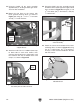
G0601 Power Connection
The incoming power wires must be connected to
the three terminals on the master power switch
marked 1L1, 3L2, and 5L3, and the incoming
ground wire must be connected the ground ter-
minal shown in Figure 41. All wires must have
adequate slack and be clear of sharp objects.
Figure 41. G0601 mag switch to power supply
connection.
A1
Ground
2T1 6T3
14NO
4T2
1L1 5L3
13NO
3L2
NHD C-18D
2T1 4T2 6T3
98 97
A2
96
O R
95
11
12
13
14
NHD NTH-14
A2
Figure 39. Typical hardwire setup with a locking
disconnect switch.
Power
Source
Locking
Disconnect Switch
Machine
Ground
Ground
ConduitConduit