MODEL G0671/G0672/G0673 DUST COLLECTOR OWNER'S MANUAL (For models manufactured since 6/17) G0671 4 HP 220V Single-Phase G0672 5 HP 220V Single-Phase G0673 10 HP 220/440V 3-Phase COPYRIGHT © MAY, 2008 BY GRIZZLY INDUSTRIAL, INC. REVISED NOVEMBER, 2017 (HE) WARNING: NO PORTION OF THIS MANUAL MAY BE REPRODUCED IN ANY SHAPE OR FORM WITHOUT THE WRITTEN APPROVAL OF GRIZZLY INDUSTRIAL, INC. #BLJB10749 PRINTED IN TAIWAN V4.11.
This manual provides critical safety instructions on the proper setup, operation, maintenance, and service of this machine/tool. Save this document, refer to it often, and use it to instruct other operators. Failure to read, understand and follow the instructions in this manual may result in fire or serious personal injury—including amputation, electrocution, or death. The owner of this machine/tool is solely responsible for its safe use.
Table of Contents INTRODUCTION................................................ 2 Machine Description....................................... 2 Contact Info.................................................... 2 Manual Accuracy............................................ 2 Identification.................................................... 3 G0671 Machine Data Sheet........................... 4 G0672 Machine Data Sheet........................... 7 G0673 Machine Data Sheet.........................
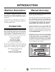
INTRODUCTION Machine Description Manual Accuracy This machine is designed to capture dust and wood chips from multiple woodworking machines at the same time, such as table saws, jointers, and planers. We are proud to provide a high-quality owner’s manual with your new machine! A wide variety of accessories for setting up a stationary or mobile dust collection system are available through Grizzly.
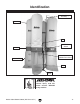
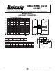
Identification Upper Bag Hanger Assembly Upper Bag Inlet ON/OFF Power Switch Collector Motor (Hidden From View) Collection Bag Base Caster To reduce your risk of serious injury, read this entire manual BEFORE using machine. Model G0671/G0672/G0673 (Mfd.
MACHINE DATA SHEET Customer Service #: (570) 546-9663 · To Order Call: (800) 523-4777 · Fax #: (800) 438-5901 MODEL G0671 4 HP DUST COLLECTOR Product Dimensions: Weight.............................................................................................................................................................. 270 lbs. Width (side-to-side) x Depth (front-to-back) x Height...................................................... 73-7/8 x 31-3/8 x 101-1/8 in. Footprint (Length x Width)...........
Bag Information Number of Upper Bags..................................................................................................................................... 2 Number of Lower Bags..................................................................................................................................... 2 Upper Bag Diameter............................................................................................................................ 23-5/8 in. Upper Bag Length..............
MACHINE DATA SHEET Customer Service #: (570) 546-9663 • To Order Call: (800) 523-4777 • Fax #: (800) 438-5901 MODEL G0671 4 HP DUST COLLECTOR 4000 3750 3500 3250 3000 2750 2500 2250 2000 1750 1500 1250 1000 750 500 250 0 CFM Performance Curve 3552 471/4" 471/4" Ø235/8" 6 /8" 5 Ø235/8" 6 5/8" 1077/8" 54" 0 1.0 2.0 3.0 4.0 5.0 6.0 7.0 8.0 9.0 Ø235/8" 54" 10.0 11.0 12.0 13.0 14.0 STATIC PRESSURE (Inch/H2O) 4 HP DUST COLLECTOR PERFORMANCE RESULTS Max CFM Max SP HP Volts Inlet 3551.6 13.
G0672 Machine Data Sheet MACHINE DATA SHEET Customer Service #: (570) 546-9663 · To Order Call: (800) 523-4777 · Fax #: (800) 438-5901 MODEL G0672 5 HP INDUSTRIAL DUST COLLECTOR Product Dimensions: Weight.............................................................................................................................................................. 286 lbs. Width (side-to-side) x Depth (front-to-back) x Height.........................................................................
Bag Information Number of Upper Bags..................................................................................................................................... 2 Number of Lower Bags..................................................................................................................................... 2 Upper Bag Diameter............................................................................................................................ 23-5/8 in. Upper Bag Length..............
MACHINE DATA SHEET Customer Service #: (570) 546-9663 • To Order Call: (800) 523-4777 • Fax #: (800) 438-5901 MODEL G0672 5 HP DUST COLLECTOR Performance Curve 4500 4250 4000 3750 3500 3250 3000 2750 2500 2250 2000 1750 1500 1250 1000 750 500 250 0 CFM 3961 Ø235/8" 70" Ø235/8" 70" 6 5/8" 130 5/8" 6 5/8" 54" Ø235/8" 57" 0 1.0 2.0 3.0 4.0 5.0 6.0 7.0 8.0 9.0 Inlet Dia. (inch) CFM Static Pressure 10.0 11.0 12.0 13.0 14.0 15.0 475/8" 475/8" Impeller 15" 313/8" 10" 3960.6 5.
MACHINE DATA SHEET Customer Service #: (570) 546-9663 · To Order Call: (800) 523-4777 · Fax #: (800) 438-5901 MODEL G0673 10 HP INDUSTRIAL DUST COLLECTOR Product Dimensions: Weight.............................................................................................................................................................. 410 lbs. Width (side-to-side) x Depth (front-to-back) x Height......................................................................... 61 x 61 x 134 in.
Bag Information Number of Upper Bags..................................................................................................................................... 4 Number of Lower Bags..................................................................................................................................... 4 Upper Bag Diameter............................................................................................................................ 23-5/8 in. Upper Bag Length..............
MACHINE DATA SHEET Customer Service #: (570) 546-9663 • To Order Call: (800) 523-4777 • Fax #: (800) 438-5901 MODEL G0673 10 HP DUST COLLECTOR Performance Curve 5500 5250 5000 4750 4500 4250 4000 3750 3500 3250 3000 2750 2500 2250 2000 1750 1500 1250 1000 750 500 250 0 5359.7 Ø235/8" 70" 81/2" 1321/2" Ø235/8" 54" 551/2" 0 1.0 2.0 3.0 CFM 4.0 5.0 6.0 7.0 8.0 9.0 10.0 11.0 12.0 CFM Static Pressure 14.0 15.0 16.0 17.0 18.0 19.
SECTION 1: SAFETY For Your Own Safety, Read Instruction Manual Before Operating This Machine The purpose of safety symbols is to attract your attention to possible hazardous conditions. This manual uses a series of symbols and signal words intended to convey the level of importance of the safety messages. The progression of symbols is described below. Remember that safety messages by themselves do not eliminate danger and are not a substitute for proper accident prevention measures.
WEARING PROPER APPAREL. Do not wear clothing, apparel or jewelry that can become entangled in moving parts. Always tie back or cover long hair. Wear non-slip footwear to reduce risk of slipping and losing control or accidentally contacting cutting tool or moving parts. HAZARDOUS DUST. Dust created by machinery operations may cause cancer, birth defects, or long-term respiratory damage. Be aware of dust hazards associated with each workpiece material.
Additional Safety for Dust Collectors Long-term respiratory damage can occur from using dust collectors without proper use of a respirator. Fire or explosions can result in smoke inhalation, serious burns, or death—if machine is used to collect incorrect materials, is operated near potential explosion sources, or ducting is improperly grounded. Entanglement, amputation, or death can occur if hair, clothing, or fingers are pulled into the inlet.
SECTION 2: POWER SUPPLY Availability Before installing the machine, consider the availability and proximity of the required power supply circuit. If an existing circuit does not meet the requirements for this machine, a new circuit must be installed. To minimize the risk of electrocution, fire, or equipment damage, installation work and electrical wiring must be done by an electrician or qualified service personnel in accordance with all applicable codes and standards.
G0671 Circuit Requirements for 220V Connection Type This machine is prewired to operate on a power supply circuit that has a verified ground and meets the following requirements: A permanently connected (hardwired) power supply is typically installed with wires running through mounted and secured conduit. A disconnecting means, such as a locking switch (see following figure), must be provided to allow the machine to be disconnected (isolated) from the power supply when required.
G0673 440V Conversion The Model G0673 can be converted for 440V operation. This conversion job consists of disconnecting the machine from the power source, changing the connections on the magnetic switch and rewiring the motor for 440V operation. The Model G0673 440V Conversion Kit (Part #P0673036) for this procedure can be purchased by calling Grizzly Customer Service at (800) 5234777. 3. Install the 440V magnetic switch and wire it according to the G0673 Wiring Diagram on Page 45. 4.
SECTION 3: SETUP Needed for Setup This machine presents serious injury hazards to untrained users. Read through this entire manual to become familiar with the controls and operations before starting the machine! Wear safety glasses during the entire setup process! HEAVY LIFT! Straining or crushing injury may occur from improperly lifting machine or some of its parts. To reduce this risk, get help from other people and use a forklift (or other lifting equipment) rated for weight of this machine.
G0671/G0672 Inventory A B The following is a list of items shipped with your machine. Before beginning setup, lay these items out and inventory them. If any non-proprietary parts are missing (e.g. a nut or a washer), we will gladly replace them; or for the sake of expediency, replacements can be obtained at your local hardware store. NOTICE E Figure 3. G0671/G0672 Inventory 1. If you cannot find an item on this list, carefully check around/inside the machine and packaging materials.
G0673 Inventory B C The following is a list of items shipped with your machine. Before beginning setup, lay these items out and inventory them. A If any non-proprietary parts are missing (e.g. a nut or a washer), we will gladly replace them; or for the sake of expediency, replacements can be obtained at your local hardware store. NOTICE If you cannot find an item on this list, carefully check around/inside the machine and packaging materials.
Site Considerations Weight Load Physical Environment Refer to the Machine Data Sheet for the weight of your machine. Make sure that the surface upon which the machine is placed will bear the weight of the machine, additional equipment that may be installed on the machine, and the heaviest workpiece that will be used. Additionally, consider the weight of the operator and any dynamic loading that may occur when operating the machine.
Assembly 4. Attach the four casters to the legs by threading them into the bottom of the legs, as shown in Figure 11. To assemble the dust collector: Caster 1. With assistance, place the impeller housing on the floor so that the motor is pointing up. 2. Insert the legs into the leg mounting brackets and secure them with the eight 5⁄16"-18 x 2 1⁄2" hex bolts and 5⁄16"-18 hex nuts, as shown in Figure 8. Do not yet fully tighten the nuts. Leg x4 Leg x8 Figure 10. Attaching casters.
Note: The Model G0673 is a three-phase machine. If it is wired out of phase, the machine may not function properly. Proceed to Test Run on Page 26 to determine if your machine is wired in phase, then proceed to Step 7. 9. Mount the hanger assembly on the protruding rod on the collector with one (Model G0671/ G0672) or two (Model G0673) 1⁄4"-20 x 1⁄2" hex bolts, as shown in Figure 14. Hanger Assembly The Models G0671 and G0672 are single phase and cannot be wired out of phase.
13. Thread the bag clamp into and around the bottom seam of the upper collection bag (see Figure 16). Collector Hook Bag Clamp Figure 17. Bottom collection bag snagged on collector hooks. Figure 16. Upper filter bag secured to collector. 14. Slip the bottom of the bag with the clamp over the top lip of the collector. 18. Wrap the bag clamp around the collector, position it between the bottom lip of the collector and the hooks, and fasten the bag clamp to secure the bag to the collector (see Figure 18).
Test Run 5. Once the assembly is complete, test run your machine to make sure it runs properly and is ready for regular operation. The test run consists of verifying the following: 1) The motor powers up and runs correctly, and 2) (Model G0673 only), the motor turns the correct direction (machine is not wired out of phase). If, during the test run, you cannot easily locate the source of an unusual noise or vibration, stop using the machine immediately, then review the Troubleshooting on Page 40.
SECTION 4: DESIGNING THE SYSTEM General Duct Material The Model G0671/G0672/G0673 can be operated as either a stationary or mobile unit. There are advantages and disadvantages to both set-ups. The advantage of the mobile system is eliminating the cost of many ducts and fittings. On the other hand, the stationary system is more versatile and convenient. You have many choices regarding main line and branch line duct material.
There are quite a number of options when it comes to metal duct, but metal duct that is specially manufactured for dust collection is the best choice. When selecting your metal duct, choose high quality metal duct with smooth welded internal seams that will minimize airflow resistance. This type of duct usually connects to other ducts or elbows with a simple, self-sealing clamp, is very quick and easy to assemble, and can be readily dismantled and re-installed.
System Design Step 1. Decide Who Will Design For most small-to-medium sized shops, you can design and build the dust collection system yourself without hiring engineers or consultants. We have included some basic information here to get you started on a dust collection system design. If you have a large shop or must design a complicated system, then we recommend that you perform additional research beyond this manual, or seek help from an expert. Step 3.
3. Directional changes should be kept to a minimum. The more directional change fittings you use directly increases the overall resistance to airflow. 4. Gradual directional changes are more efficient than sudden directional changes (i.e. use the largest corner radius possible when changing hose or pipe direction). 5. Each branch line should have a blast gate immediately after the branch to control suction from one machine to another. 6.
Determining Main Line Duct Size The general rule of thumb for a main line duct is that the velocity of the airflow must not fall below 3500 FPM. Use the inlet size of the dust collector as a starting point for the main line. Neck the main line down 1" for every 10' of length. This will usually keep the air velocity above 3500 FPM and, depending on your system, will allow you to keep multiple branches open at one time. For the Model G0671/G0672/G0673 this is 10". Mark your drawing, as in Figure 28.
Calculating Duct Resistance Adding duct work, elbows, branches and any other components to a duct line increases airflow resistance (static pressure loss). This resistance can be minimized by using rigid (smooth) pipe and gradual curves, as opposed to flexible pipe and 90˚ elbows. To help you think about this resistance, imagine riding a bicycle in a tunnel that is an exact replica of your duct work.
model G067 4 HP dUST Colle 4. Total your list, as shown in the example in Figure 33, to come up with your overall static pressure loss number for that line. Note: Always account for a seasoned filter, so you don't end up with a system that only works right when the filter is clean. Main Line 6" Rigid Pipe (0.037) at 20' ................ 0.740 Branch Line 4" Rigid Pipe (0.075) at 10' ................ 4" Flex Pipe (0.28) at 5' ........................ 0.750 1.400 Elbows/Branches 6" 45˚ Y-Branch ........
System Grounding Since plastic hose is abundant, relatively inexpensive, easily assembled and air tight, it is a very popular material for conveying dust from woodworking machines to the dust collector. We recommend using flexible hose (flex-hose) to connect the woodworking machine to the dust collection system. However, plastic flex-hose and plastic duct are insulators, and dust particles moving against the walls of the plastic duct create static electrical build up.
SECTION 5: OPERATIONS Basic Controls To reduce your risk of serious injury, read this entire manual BEFORE using machine. This section covers the basic controls used during routine operations: ON Button: Starts the motor. OFF Button: Stops the motor. Eye injuries, respiratory problems, or hearing loss can occur while operating this tool. Wear personal protective equipment to reduce your risk from these hazards. ON OFF Keep hair, clothing, and jewelry away from moving parts at all times.
ACCESSORIES SECTION 6: ACCESSORIES Installing unapproved accessories may cause machine to malfunction, resulting in serious personal injury or machine damage. To reduce this risk, only install accessories recommended for this machine by Grizzly. H5294—4" Metal Duct Machine Addition Kit H5296—5" Metal Duct Machine Addition Kit H5298—6" Metal Duct Machine Addition Kit Save over 20% with this great machine addition kit.
Metal Elbows These industrial metal elbows are available from 4"–8" with 90˚, 60˚, 45˚, or 30˚ curves. Also, available with a 90˚ long radius curve. Call (800) 5234777 or visit www.grizzly.com for more information and pricing. 90° Metal Branches We carry many different branches, all designed to minimize airflow resistance. 90° Long Radius Figure 43. Metal Branches. 30° 45° 60° Reducers & Adapters We carry a multitude of reducers and elbows to cover most applications from 4" through 9". Figure 41.
H4978—Deluxe Earmuffs - 27dB H4979—Twin Cup Hearing Protector - 29dB T20446—Ear Plugs 200 Pair - 31dB Protect your hearing before its too late. Especially important if you or employees operate for hours at a time. G0572—Hanging Air Filter With Remote This Hanging Air Filter has a convenient remote control and features a three speed motor, automatic shutoff timer and 1 micron inner filter and 5 micron outer filter. Air flow is 556, 702, and 1044 CFM. H4978 H4979 T20446 G0572 Figure 45.
SECTION 7: MAINTENANCE Bag Cleaning Disconnect power to the machine when performing any maintenance, assembly or adjustments. Failure to do this may result in serious personal injury. Keep loose clothing rolled up and out of the way of machinery and keep hair pulled back. Schedule For optimum performance from your machine, follow this maintenance schedule and refer to any specific instructions given in this section. Daily Check: • Dust collector is completely powered down at the end of use.
SECTION 8: SERVICE Review the troubleshooting and procedures in this section if a problem develops with your machine. If you need replacement parts or additional help with a procedure, call our Technical Support. Note: Please gather the serial number and manufacture date of your machine before calling. Troubleshooting Motor & Electrical Symptom Possible Cause Possible Solution Machine does not start or a breaker trips. 1. Plug/receptacle is at fault or wired incorrectly.
Dust Collection Operation SYMPTOM POSSIBLE CAUSE CORRECTIVE ACTION 1. Stabilize the dust collector. 2. Loud, repetitious noise, or 1. excessive vibration coming from dust collector. 2. Dust collector is not on a flat surface and wobbles. Impeller fan is damaged and unbalanced. 3. The motor mounting is loose. 3. 4. Impeller is loose on the motor shaft. Motor fan cover is dented, causing the motor fan to hit the cover while spinning. 4. 5.
machine SECTION 9: WIRING These pages are current at the time of printing. However, in the spirit of improvement, we may make changes to the electrical systems of future machines. Compare the manufacture date of your machine to the one stated in this manual, and study this section carefully. If there are differences between your machine and what is shown in this section, call Technical Support at (570) 546-9663 for assistance BEFORE making any changes to the wiring on your machine.
G0671 Wiring Diagram Wt Bk A Bk Bk L1/1 Gn L2/3 7 L3/5 SDE MA-15 T1/2 T2/4 T3/6 8 Gn B 1/2 3/4 5/6 RESET AMP OFF Set to 30 22 34 28 98 96 Figure 49. G0671 MA-15 contactor. Wt Bk Bk 95 Bk Gn Bk Wt Bk Wt Gn Rd Rd Bk Wt Gn Ground Rd Rd Rd Rd Run Capacitor 50MFD 300VAC Start Capacitor 600MFD 250VAC Wt Bk Figure 50. G0671 motor junction box. Gn MOTOR at 220V SINGLE-PHASE Hot GND Locking Shut-Off Switch (As Recommended) Model G0671/G0672/G0673 (Mfd.
G0672 Wiring Diagram Wt Bk Bk Bk Gn A R/1/L1 S/3/L2 T/5/L3 21NC 13 SDE 14 MA-30 T1/2 T2/4 T3/6 22NC Gn B 1/2 3/4 5/6 42 RESET AMP OFF Set to 37 28 35 RA-30 98 96 Wt Bk Bk 95 Bk Figure 51. G0672 MA-30 contactor. Gn Bk Bk Wt Wt Gn Start Capacitor Rd Bk Start Capacitor 800MFD 250VAC Figure 52. G0672 start capacitor.
G0673 Wiring Diagram MOTOR DIRECTION If motor rotates in opposite direction, swap any two power source wires at the incoming terminals. Ground Hot Gn Bk Wt Rd DISCONNECT SWITCH (as recommended) Hot Rd Ground 3-PHASE 440 VAC 3-PHASE 220 VAC Hot Bk Hot Gn Wt Hot Hot See Figure 54 on Page 46.
G0673 Electrical Components Figure 54. G0673 220V switch. -46- READ ELECTRICAL SAFETY ON PAGE 42! Figure 55. G0673 220V motor. Model G0671/G0672/G0673 (Mfd.
SECTION 10: PARTS G0671 Parts Breakdown 16 16 20V2 14 13 6 19 20V2 17 10 11 17 15 30 19 7 8 15 9 18 17 17 28 12 29 40 28 1-1 30 40 18 1-3 4 2 34 35 1 19 39 1-5 3 41 1-6 1-7 36 23 24 38V2 22 42 21 21 22 38V2 19 31 33 32 5 1-2 1-4 29 27 26 33-2 33-2A 33-4 1-8 27 26 25 Model G0671/G0672/G0673 (Mfd.
G0671 Parts List REF PART # DESCRIPTION REF PART # DESCRIPTION 1 1-1 1-2 1-3 1-4 1-5 1-6 1-7 1-8 2 3 4 5 6 7 8 9 10 11 12 13 14 15 16 17 18 19 20V2 MOTOR 4HP, 220V, 1 PH FAN COVER FAN S CAPACITOR COVER S CAPACITOR 600M 250V X 1-3/4 X 3-7/8 R CAPACITOR COVER R CAPACITOR 50M 300V X 1-3/4 X 2-3/4 JUNCTION BOX CENTRIFUGAL SWITCH HEX NUT 3/8-16 LOCK WASHER 3/8 KEY 6 X 6 X 25 MOTOR GASKET HEX BOLT 5/16-18 X 3/4 INLET COVER IMPELLER 14-1/2" HEX BOLT 3/8-16 X 1/2 CAP SCREW M6-1 X 20 FLAT WASHER 6MM COLLECTOR H
G0672 Parts Breakdown 16 16 20 14 13 6 19 20 17 10 11 17 15 17 28 12 40 29 30 18 4 33V3 2 1 19 19 31 32 40 5 1-2 1-5 18 17 28 1-1 1-4 8 9 15 30 29 19 7 34 35 39 3 1-6 38 41 22 42 21 21 22 1-7 38 24 36 23 27 26 33-2V2 33-6 33-4 1-8 27 26 25 Model G0671/G0672/G0673 (Mfd.
G0672 Parts List REF PART # DESCRIPTION REF PART # DESCRIPTION 1 1-1 1-2 1-4 1-5 1-6 1-7 1-8 2 3 4 5 6 7 8 9 10 11 12 13 14 15 16 17 18 19 20 21 P0672001 P0672001-1 P0672001-2 P0672001-4 P0672001-5 P0672001-6 P0672001-7 P0672001-8 P0672002 P0672003 P0672004 P0672005 P0672006 P0672007 P0672008 P0672009 P0672010 P0672011 P0672012 P0672013 P0672014 P0672015 P0672016 P0672017 P0672018 P0672019 P0672020 P0672021 MOTOR 5HP, 220V, 1 PH FAN COVER FAN S CAPACITOR 800M 250V 1-3/4 X 3-3/4 R CAPACITOR COVER R C
G0673 Parts Breakdown 16 16 20 20 16 16 20 17 20 15 15 15 17 19 17 14 19 34 18 18 37 27 440V 15 36 13 19 29 19 30 40 28 18 37 31 12 9 19 30-4 22 10 21 30-2 32 33 11 220V 8 7 23 21 19 18 30-1 30-3 30-5 21 24 24 25 2 3 25 26 38 5 6 4 24 24 26 1 1-1 35 26 21 1-2 1-3 Model G0671/G0672/G0673 (Mfd.
G0673 Parts List REF PART # DESCRIPTION REF PART # DESCRIPTION 1 1-1 1-2 1-3 2 3 4 5 6 7 8 9 10 11 12 13 14 15 16 17 18 19 20 21 22 23 24 MOTOR 10HP, 220V, 3 PH FAN COVER FAN JUNCTION BOX HEX NUT 1/2"-12 LOCK WASHER 1/2 KEY 8 X 8 X 25 MOTOR GASKET HEX BOLT 5/16-18 X 3/4 INLET COVER HEX BOLT 1/2 X 1-1/2 IMPELLER 17" HEX BOLT 3/8-16 X 1-1/2 FLAT WASHER 6MM CAP SCREW M6-1 X 20 COLLECTOR HOUSING INLET ADAPTER BAG HANGER LOWER SUPPORT BAG HANGER HEX BOLT 1/4-20 X 1/2 COLLECTOR DRUM BAG CLAMP FILTER BAG 2.
Label Placement G0672 G0671 50 50 51 51 56 56 55 55 52 54 53 52 54 53 G0673 51 56 55 REF PART # DESCRIPTION 50 51 51 51 52 52 53 54 55 56 HANDS INLET WARNING (G0671, G0672) MACHINE ID LABEL (G0671) MACHINE ID LABEL (G0672) MACHINE ID LABEL (G0673) GRIZZLY NAMEPLATE (G0671, G0672) GRIZZLY NAMEPLATE (G0673) EAR PROTECTION 2" X 3-5/16"H GLASSES/RESPIRATOR READ MANUAL-VERTICAL NS 7/05 GRIZZLY GREEN TOUCH-UP PAINT P0671050 P0671051 P0672051 P0673051 P0671052 P0673052 P0671053 P0671054 P067
WARRANTY CARD Name _____________________________________________________________________________ Street _____________________________________________________________________________ City _______________________ State _________________________ Zip _____________________ Phone # ____________________ Email _________________________________________________ Model # ____________________ Order # _______________________ Serial # __________________ The following information is given on a voluntary basis.
FOLD ALONG DOTTED LINE Place Stamp Here GRIZZLY INDUSTRIAL, INC. P.O.
WARRANTY AND RETURNS WARRANTY AND RETURNS Grizzly Industrial, Inc. warrants every product it sells for a period of 1 year to the original purchaser from the date of purchase. This warranty does not apply to defects due directly or indirectly to misuse, abuse, negligence, accidents, repairs or alterations or lack of maintenance.