
Use and Care Manual


-26-
Model G0694 (Mfd. Since 03/15)
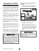
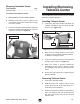
4. Position the belt on the motor and spindle
pulleys for the correct speed range.
5. Loosen the lock lever and allow the motor
weight to tension the belt. There should be
almost no belt looseness or belt deflection.
Note: If the motor does not hang freely
against the belt, you may have to manually
push the height lever to tension the belt.
6. Tighten the lock lever.
7. Close the belt access panel and cabinet
door.
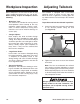
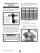
Indexing
Indexing on a lathe is typically used for workpiece
layout and other auxiliary operations that require
equal distances around the workpiece circumfer-
ence, such as clock faces or inlays.
By applying the spindle lock into one of the 24
holes in the spindle, the workpiece can be posi-
tioned to one of 24 equal points that are 15°
degrees apart.
For special sequencing of positions, each spindle
position has its own number, which can be viewed
through the viewing window, as shown in Figure
26, on the outboard side of the headstock.
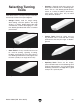
3. Open the cabinet door, loosen the lock
lever, pull up on the height lever to raise the
motor to the highest position, then re-tighten
the lock lever to secure the motor in place
(Figure 25).
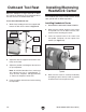
NOTICE
Always disconnect the lathe from power
before using the spindle lock feature. Never
resume turning operations without making
sure that the spindle lock is disengaged and
the spindle turns freely by hand. Otherwise
machine damage could result.
Figure 25. Motor lock and height levers.
Height
Lever
Figure 26. Spindle lock lever and viewing
window.
Numbered
Holes
Shown
Through
Viewing
Window.
Spindle Lock
Lock Lever