
Use and Care Manual

Model G0694 (Mfd. Since 03/15)
-43-
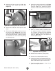
5. Unthread the lock nut on the spindle lock
mechanism, then remove the unit (see
Figure 59).
6. Remove the end plate, then open the belt
cover.
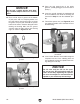
7. Remove the Phillips head screws that secure
the speed sensor (Figure 60), then reach
inside the headstock and rest the sensor cord
over the internal crossbar, or bring it outside
the headstock so it is out of the way during
the following steps.
Figure 60. Removing speed sensor screws.
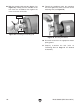
9. While an assistant holds the inboard end of
the spindle and pulls it toward the tailstock,
use a hammer and 2x4 to drive the outboard
end of the spindle toward the tailstock, as
shown in Figure 62. This will expose the
inboard spindle bearing.
Figure 62. Loosening spindle.
10. Remove the belt from the spindle pulley.
11. Remove the outboard spindle bearing.
12. Inspect the inboard and outboard roller bear-
ings for pitting, cracks or heavy wear. Replace
them if either shows signs of serious wear.
13. Clean the spindle bearings using mineral
spirits and compressed air.
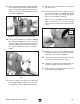
8. Loosen the motor tension lock (see Figure
61), raise the motor up as far as possible
using the height lever, tighten the tension
lock, then remove the belt from the motor pul-
ley.
Figure 59. Removing spindle lock mechanism.
Spindle Lock
End
Plate
Figure 61. Motor tension controls.
Height Lever
Motor Tension
Lock