MODEL G0703/G0703P 1 1⁄ 2 HP CYCLONE DUST COLLECTOR OWNER'S MANUAL (For models manufactured since 04/19) Model G0703 Model G0703P COPYRIGHT © AUGUST, 2009 BY GRIZZLY INDUSTRIAL, INC. REVISED APRIL, 2019 (JL) WARNING: NO PORTION OF THIS MANUAL MAY BE REPRODUCED IN ANY SHAPE OR FORM WITHOUT THE WRITTEN APPROVAL OF GRIZZLY INDUSTRIAL, INC. #TRCRBLTSJB11940 PRINTED IN TAIWAN V3.04.
This manual provides critical safety instructions on the proper setup, operation, maintenance, and service of this machine/tool. Save this document, refer to it often, and use it to instruct other operators. Failure to read, understand and follow the instructions in this manual may result in fire or serious personal injury—including amputation, electrocution, or death. The owner of this machine/tool is solely responsible for its safe use.
Table of Contents INTRODUCTION................................................ 2 Manual Accuracy............................................ 2 Contact Info.................................................... 2 Machine Description....................................... 2 Identification.................................................... 3 Glossary Of Terms.......................................... 4 Machine Data Sheet....................................... 5 SECTION 1: SAFETY.................................
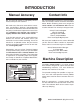
INTRODUCTION Manual Accuracy Contact Info We are proud to provide a high-quality owner’s manual with your new machine! We stand behind our machines! If you have questions or need help, contact us with the information below. Before contacting, make sure you get the serial number and manufacture date from the machine ID label. This will help us help you faster. We made every effort to be exact with the instructions, specifications, drawings, and photographs in this manual.
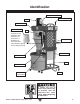
Identification Remote Relay Switch Filter Brush Handle Motor Blower Housing Inlet Restrictor Note: The inlet restrictor is only installed if dust collector is to be used on a 20 Amp-110 Volt circuit and circuit breaker tripping occurs during start-up. Inlet Canister Filter Collection Bag Cyclone Funnel Stand Collection Drum Drum Ground Wire Caster Figure 1. Identification.
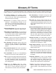
Glossary Of Terms The following is a list of common definitions, terms and phrases that relate to dust collection and dust collectors in general. To get the most out of this manual, familiarize yourself with these terms before reading. Air Suction Capacity: The maximum volume of air (rated in CFM) that a dust collector can move, at the inlet, when fully assembled and not connected to any ducting.
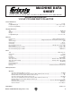
Machine Data Sheet MACHINE DATA SHEET Customer Service #: (570) 546-9663 • To Order Call: (800) 523-4777 • Fax #: (800) 438-5901 MODELS G0703/G0703P MODEL G0703 1-1/2HP HPCYCLONE CYCLONE DUST DUST COLLECTOR 1-1/2 COLLECTOR Product Dimensions: Weight ........................................................................................................................................................................... 177 lbs. Length/Width/Height ...........................................................
Main Specifications: Operation Air Suction Capacity (30A, w/o 5" Port) .............................................................................................................775 CFM Static Pressure at Maximum Air Suction Capacity (30A, 110V Circuit w/o 5" Port) ................................................ 1.80" Maximum Static Pressure (30A, 110V Circuit w/o 5" Port) .........................................................................................
SECTION 1: SAFETY For Your Own Safety, Read Instruction Manual Before Operating This Machine The purpose of safety symbols is to attract your attention to possible hazardous conditions. This manual uses a series of symbols and signal words intended to convey the level of importance of the safety messages. The progression of symbols is described below. Remember that safety messages by themselves do not eliminate danger and are not a substitute for proper accident prevention measures.
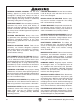
WEARING PROPER APPAREL. Do not wear clothing, apparel or jewelry that can become entangled in moving parts. Always tie back or cover long hair. Wear non-slip footwear to reduce risk of slipping and losing control or accidentally contacting cutting tool or moving parts. HAZARDOUS DUST. Dust created by machinery operations may cause cancer, birth defects, or long-term respiratory damage. Be aware of dust hazards associated with each workpiece material.
Additional Safety for Dust Collectors INTENDED USE. This dust collector is only intended for collecting wood dust and chips from woodworking machines. DO NOT use this dust collector to collect metal, dirt, pebbles, drywall, asbestos, lead paint, silica, liquids, aerosols, or any flammable, combustible, or hazardous materials. HAZARDOUS DUST. Dust created while using machinery may cause cancer, birth defects, or long-term respiratory damage.
SECTION 2: POWER SUPPLY Availability Circuit Information Before installing the machine, consider the availability and proximity of the required power supply circuit. If an existing circuit does not meet the requirements for this machine, a new circuit must be installed. To minimize the risk of electrocution, fire, or equipment damage, installation work and electrical wiring must be done by an electrician or qualified service personnel in accordance with all applicable codes and standards.
Circuit Requirements for 220V This machine can be converted to operate on a power supply circuit that has a verified ground and meets the requirements listed below. (Refer to Voltage Conversion instructions for details.) Nominal Voltage............................... 220V/240V Cycle...........................................................60 Hz Phase............................................ Single-Phase Circuit Rating....................................... 15 Amps Plug/Receptacle........................
Improper connection of the equipment-grounding wire can result in a risk of electric shock. The wire with green insulation (with or without yellow stripes) is the equipment-grounding wire. If repair or replacement of the power cord or plug is necessary, do not connect the equipment-grounding wire to a live (current carrying) terminal.
MOTOR 110V 4. Remove the wire nuts indicated in Figure 6. 6. Run Start Capacitor Capacitor Remove the wires connected to the circuit 40MFD 300MFD 250VAC 125VAC board, as indicated in Figure 8. 1 4 2 3 Circuit Board 220V Run Capacitor 40MFD 250VAC Start Capacitor 300MFD 125VAC 1 3 2 4 Remove L2 Circuit Breaker Remove M2 M1 Figure 6. Motor wires at 110V. COM Circuit Board 110V 5. Connect the motor wires, as shown in Figure 7, with wire nuts.
SECTION 3: SETUP Needed for Setup This machine presents serious injury hazards to untrained users. Read through this entire manual to become familiar with the controls and operations before starting the machine! The following items are needed to complete the setup process, but are not included with your machine: Description Qty • Assistant...................................................... 1 • Safety Glasses................... For Each Person • Wrench 3 ⁄ 8"..............................................
Hardware Recognition Chart 5mm Model G0703/G0703P (Mfg.
Inventory The following is a list of items shipped with your machine. Before beginning setup, lay these items out and inventory them. If any non-proprietary parts are missing (e.g. a nut or a washer), we will gladly replace them; or for the sake of expediency, replacements can be obtained at your local hardware store. Machine Inventory (Figure 9): Qty A. Dust Collector & Filter Assembly................. 1 B. Remote Control...........................................
Site Considerations Weight Load Physical Environment Refer to the Machine Data Sheet for the weight of your machine. Make sure that the surface upon which the machine is placed will bear the weight of the machine, additional equipment that may be installed on the machine, and the heaviest workpiece that will be used. Additionally, consider the weight of the operator and any dynamic loading that may occur when operating the machine.
Assembly 4. To assemble the dust collector: 1. Position the stand over the dust collector housing, as shown in Figure 15, and install (1) 5⁄16"-18 x 11⁄2" hex bolt and flat washer on each side of the stand to serve as pivot bolts (leave bolts loose for now). Invert the stand, place a 3⁄8" lock washer on each of the four caster wheel studs. Then thread each caster into the stand, and using a 3 ⁄8" wrench, tighten each caster stud onto the stand (see Figure 13).
8. Install the handle with (4) 5⁄16"-18 x 3⁄4" hex bolts and (4) 5⁄16" washers, as shown in Figure 17. 10. Attach the casters to the bottom of the drum using (4) 3⁄8"-16 nuts, (4) 3⁄8" flat washers, and (4) 3⁄8" lock washers (see Figure 19). Handle x4 x4 Figure 17. Installing the hand rail. 9. Install the hand crank on the shaft with (1) ⁄16"-18 x 3⁄4" hex bolt and (1) 5⁄16" flat washer, as shown in Figure 18. 5 Figure 19. Dust collection drum casters installed. 11.
12. Place the drum extender onto the drum, see Figure 21. 14. Place the dust collection bag seat into the duct collection drum, as shown in Figure 23. Drum Extender Drum Clamp Drum Figure 21. Drum extender on drum. Figure 23. Installing the dust collection bag seat. 13. Secure the drum extender to the drum with the drum clamp. Use (1) 5⁄16"-18 x 3" hex bolt and (1) 5⁄16"-18 hex nut to secure the clamp (see Figure 22). 15. Insert the rubber seal over the top lip of the drum rim, as shown in Figure 24.
16. Install the dust collection bag into the collection drum as shown in Figure 25. 18. Connect the 1" hose and the 7" hose to the collection drum. 19. Connect the other end of both hoses to the cyclone housing (see Figure 27), and secure them in place with the appropriate diameter hose clamps. Figure 25. Bag installation. 17. Place the drum lid onto the drum and tighten the latches, then roll the drum under the cyclone port so the drum spout faces the dust collector, as shown in Figure 26.
Power Connection After you have completed all previous setup instructions and circuit requirements, the machine is ready to be connected to the power supply. Disconnecting Power 1. Turn the machine power switch OFF. 2. Grasp the molded plug and pull it completely out of the receptacle. DO NOT pull by the cord as this may damage the wires inside. To avoid unexpected startups or property damage, use the following steps whenever connecting or disconnecting the machine from the power supply.
Test Run 4. When the assembly is complete, test run your dust collection system to make sure it operates properly. IR Sensor Power Switch NOTICE If you still cannot remedy a problem, contact our Tech Support at (570) 546-9663 for assistance. Remote Control Figure 30. G0703P controls. 5. Press the ON/OFF button to turn the machine ON. Make sure your hand stays poised over the switch in case you need to quickly turn the machine OFF. 6. Listen to and watch for abnormal noises or actions.
SECTION 4: DESIGNING THE SYSTEM General The Model G0703/G0703P is designed to collect dust from one machine at a time. This can be accomplished by either connecting it to one machine at a time or by connecting it to multiple machines and using blast gates to control which branch is active. The Model G0703/G0703P works quite well as a point of use dust collector. The wheels make it easy to move around the shop near the machine being used.
Metal Duct Flexible Duct Advantages of metal duct is its conductivity and that it does not contribute to static electrical charge build-up. However, static charges are still produced when dust particles strike other dust particles as they move through the duct. Since metal duct is a conductor, it can be grounded quite easily to dissipate any static electrical charges. Flexible hose is generally used for short runs, small shops and at rigid duct-to-tool connections.
System Design Step 1. Decide Who Will Design For most small-to-medium sized shops, you can design and build the dust collection system yourself without hiring engineers or consultants. We have included some basic information here to get you started on a basic design. If you have a large shop or plan to design a complicated system, we recommend doing additional research beyond this manual or seeking the help of an expert. Step 2.
3. Directional changes should be kept to a minimum. The more directional change fittings you use directly increases the overall resistance to airflow. 4. Gradual directional changes are more efficient than sudden directional changes (i.e. use the largest corner radius possible when changing hose or pipe direction). 5. Each individual branch line should have a blast gate immediately after the branch to control suction from one machine to another. 6.
Determining Main Line Duct Size The general rule of thumb for a main line duct is that the velocity of the airflow must not fall below 3500 FPM. For small/medium sized shops, using the inlet size of the dust collector as the main line duct size will usually keep the air velocity above 3500 FPM and, depending on your system, will allow you to keep multiple branches open at one time. Mark your drawing, as shown in the figure below, but using the inlet size for your dust collector as the main line.
Multiple Dust Ports If your machine has multiple dust ports, add the total CFM given for each dust port size from the table provided in the earlier subsection, Determine Required CFMs, then find the closest CFM in the table below to determine the correct branch size. Split the branch line just before the dust ports with matching duct sizes. Total CFM Branch Line Size 400 4" 500 4" 600 5" 700 5" 800 6" 900 6" 1000 6" Duct Dia. Main Lines at 3500 FPM Branch Lines at 4000 FPM 2" 0.091 0.
Performance curve 3. Add the additional factors from the following table to your list. Additional Factors Seasoned (well used) Dust Collection Filter Entry Loss at Large Machine Hood Static Pressure 1" 2" Figure 45. Additional factors affecting static pressure. 4. Total your list as shown in the example below to come up with your overall static pressure loss number for that line.
— If the CFM for your static pressure loss is below the requirement of the machine, then that line will not effectively collect the dust. You must then modify some of the factors in that line to reduce the static pressure loss. Some of the ways to do this include 1) installing larger duct, 2) reducing amount of flexible duct used, 3) increasing machine dust port size, 4) moving machine closer to dust collector to eliminate duct length, and 5) reducing 90˚ elbows or replacing them with 45˚ elbows.
System Grounding Since plastic hose is abundant, relatively inexpensive, easily assembled and air tight, it is a very popular material for conveying dust from woodworking machines to the dust collector. We recommend only using short lengths of flexible hose (flex-hose) to connect the woodworking machine to the dust collector. However, plastic flex-hose and plastic duct are an insulator, and dust particles moving against the walls of the plastic duct create a static electrical buildup.
SECTION 5: OPERATIONS General Operation To reduce the risk of serious injury when using this machine, read and understand this entire manual before operating. This cyclone dust collector creates a vortex of incoming air that extracts heavy wood chips (see Figure 50) and large dust particles, and then drops them into the steel drum below, which is lined with a plastic bag. Damage to your eyes and lungs could result from using this machine without proper protective gear.
Remote Control Operation A remote control receiver and handheld controller (see Figure 51) allow the dust collector to be turned ON and OFF from across the room up to 75-feet away, providing that direct line-of-sight is maintained. The Model G0703/G0703P is equipped with a circuit breaker/thermal overload button. If the dust collector experiences an overload, this button pops out and the machine shuts down.
Replacing Canister Filter Operating Remote Receiver Refer to Figure 52 and the following descriptions to understand the receiver control functions. A G B F I E D C For a more thorough cleaning every few months (under heavy use), remove the filter from the dust collector and rinse it with warm water. Allow the filter to air dry only. Do not leave the filter in the sun to dry or apply heat or compressed air to speed the process; heat exposure can damage your filter.
4. Remove the twelve hex nuts from the blower housing base, as shown in Figure 54. 6. Figure 54. Removing hex bolts from canister assembly. 5. -36- Remove the canister assembly from the blower housing. Carefully lift the filter out of the canister assembly, as shown in Figure 55. Figure 55. Removing filter. 7. Insert a clean/new filter into the canister assembly, then re-install the canister to the blower housing base and cross support by repeating the previous steps in reverse. 8.
ACCESSORIES SECTION 6: ACCESSORIES Some aftermarket accessories can be installed on this machine that could cause it to function improperly, increasing the risk of serious personal injury. To minimize this risk, only install accessories recommended for this machine by Grizzly.
D4206—Clear Flexible Hose 4" x 10' D4256—45° Elbow 4" D4216—Black Flexible Hose 4" x 10' W1034—Heavy-Duty Clear Flex Hose 4" x 10' D2107—Hose Hanger 4 1⁄4" W1015—Y-Fitting 4" x 4" x 4" W1017—90° Elbow 4" W1019—Hose Coupler (Splice) 4" W1317—Wire Hose Clamp 4" W1007—Plastic Blast Gate 4" W1053—Anti-Static Grounding Kit Hand-picked selection of commonly used dust collection components for 4" dust ports.
SECTION 7: MAINTENANCE Cleaning Filter Always disconnect power to the machine before performing maintenance. Failure to do this may result in serious personal injury. Schedule The Model G0703/G0703P dust collector has a crank handle (see Figure 63) driven filter flap system for removing any built-up dust from the filter pleats. Crank Handle For optimum performance from your machine, follow this maintenance schedule and refer to any specific instructions given in this section.
SECTION 8: SERVICE Review the troubleshooting and procedures in this section to fix or adjust your machine if a problem develops. If you need replacement parts or you are unsure of your repair skills, then feel free to call our Technical Support at (570) 546-9663. Troubleshooting Motor & Electrical Symptom Possible Cause Possible Solution Machine does not start or a breaker trips. 1. Power supply switched OFF or is at fault. 1.
Dust Collector Operation Symptom Possible Cause Possible Solution Loud, repetitious noise, or excessive vibration coming from dust collector. 1. Dust collector is not on a flat surface and wobbles. 2. Impeller is damaged and unbalanced. 1. Stabilize the dust collector. 3. The motor mounting or housing connections are loose. 4. Impeller is loose on the motor shaft. 5. Motor fan cover is dented, causing the motor fan to hit the cover while spinning.
wiring SECTION 9: WIRING These pages are current at the time of printing. However, in the spirit of improvement, we may make changes to the electrical systems of future machines. Compare the manufacture date of your machine to the one stated in this manual, and study this section carefully. If there are differences between your machine and what is shown in this section, call Technical Support at (570) 546-9663 for assistance BEFORE making any changes to the wiring on your machine.
Electrical Component Locations Remote Receiver Figure 64. G0703/G0703P electrical component locations. Figure 65. G0703/G0703P remote receiver circuit and components. Model G0703/G0703P (Mfg.
G0703/G0703P 110V Wiring Diagram Motor 110V Run Capacitor 40MFD 250VAC Start Capacitor 300MFD 125VAC 1 3 2 4 Circuit Board 110V Circuit Breaker/ Thermal Overload L2 M2 M1 Power Switch GND COM L1 Ground Neutral W Hot Ground Neutral 110 VAC 5-20 Plug (As Recommended, With Inlet Restrictor) -44- G 110 VAC Hot L5-30 Plug (As Recommended, Without Inlet Restrictor) Model G0703/G0703P (Mfg.
G0703/G0703P 220V Wiring Diagram Motor 220V Run Capacitor 40MFD 250VAC Start Capacitor 300MFD 125VAC 1 3 2 4 Circuit Board 220V L2 Circuit Breaker/ Thermal Overload M2 M1 Power Switch GND COM L1 Ground G Hot 220 VAC Hot Model G0703/G0703P (Mfg.
SECTION 10: PARTS G0703 Breakdown 1V2-21 1V2-17 1V2-18 1V2-15 1V2-1 1V2-2 1V2-4 1V2-6 1V2-7 1V2-8 1V2-9 1V2 1V2-3 1V2-20 1V2-10 1V2-11 1V2-12 1V2-14 1V2-24 1V2-23 1V2-25 1V2-22 1V2-5 44 5 99 7 49 3 8 4 51 10-1 89 4 9 55 57 56 54V2 53 12 70 71 91 22-1 68 23 24 58-1 66V2 82 4 17 27 28 98 18 19 93 94 95 98-1 20 21 25 94 29 26 96 98-1 61 62 79 83 81 80 40 84 32 35 30 33 34 31 86 92 16-1 16 22 67 86-1 36 38 65 87 85 37 23 24 41 38-1 39 -46- 13 17 18
G0703 Parts List REF PART # DESCRIPTION REF PART # DESCRIPTION 1V2 1V2-1 1V2-2 1V2-3 1V2-4 1V2-5 1V2-6 1V2-7 1V2-8 1V2-9 1V2-10 1V2-11 1V2-12 1V2-14 1V2-15 1V2-17 1V2-18 1V2-20 1V2-21 1V2-22 1V2-23 1V2-24 1V2-25 2 3 4 5 6 7V2 8 9 10 10-1 12 13 13-1 20 21 22 22-1 23V2 24 25V2 26 27 28 29 30 31 32 33 34 35 36 P0703001V2 P0703001V2-1 P0703001V2-2 P0703001V2-3 P0703001V2-4 P0703001V2-5 P0703001V2-6 P0703001V2-7 P0703001V2-8 P0703001V2-9 P0703001V2-10 P0703001V2-11 P0703001V2-12 P0703001V2-14 P0703001V2-1
G0703P Breakdown 1-15 1-1 1-2 1-4 1-5 1-17 1-21 1-6 1-7 1-8 1-9 1-18 1-3 1-10 1-11 1-12 1-14 1-23 1-22 1 1-20 1-24 1-25 44 5 49 57 6 3 8 4 51 50 52 7 43 46 45 90 56 99 2 47 48 220V Conversion Kit 88 89 4 9 55 56 53 54V2 10-1 69 58-1 70 13-1 71 12 13 68 58 22-1 15 91 92 23 66 24 67 58-1 22 93 95 94 98-1 82 4 17 27 28 98 20 21 25 94 61 62 79 83 81 80 40 84 26 32 35 30 33 34 31 86 86-1 36 38 65 87 85 37 23 24 41 38-1 39 -48- 29 96 98-1 64
G0703P Parts List REF PART # DESCRIPTION REF PART # DESCRIPTION 1 1-1 1-2 1-3 1-4 1-5 1-6 1-7 1-8 1-9 1-10 1-11 1-12 1-13 1-14 1-15 1-17 1-18 1-19 1-20 1-21 1-22 1-23 1-24 1-25 2 3 4 5 6 7 8 9 10 10-1 11 12 13 13-1 15 17 20 21 22 22-1 23 24 25 26 27 28 29 30 31 32 33 34 35 MOTOR 1-1/2 HP 110/220V 1PH V1 MOTOR FAN COVER MOTOR FAN REMOTE RECEIVER BOX S CAPACITOR 300M 125V 1-1/2 X 3-1/8 R CAPACITOR 40M 250V 1-3/8 X 2-3/8 CIRCUIT BOARD 110V 256 CODE THERMAL OVERLOAD TRANKEY 25A REMOTE CONTROL PANEL POWER S
G0703/G0703P Labels 100 105 110 103 106 109 101 107 102 108 104 REF PART # DESCRIPTION REF PART # DESCRIPTION 100 100 101 102 103 104 104 105 MACHINE ID LABEL (G0703) MACHINE ID LABEL (G0703P) HEARING HAZARD LABEL READ MANUAL LABEL GLASSES/RESPIRATOR DC LABEL MODEL NUMBER LABEL (G0703) MODEL NUMBER LABEL (G0703P) ELECTRICITY LABEL 106 107 108 108 109 109 110 INLET HAZARD LABEL GRIZZLY GREEN TOUCH-UP PAINT GRIZZLY.COM LABEL RED GRIZZLY.
WARRANTY CARD Name _____________________________________________________________________________ Street _____________________________________________________________________________ City _______________________ State _________________________ Zip _____________________ Phone # ____________________ Email _________________________________________________ Model # ____________________ Order # _______________________ Serial # __________________ The following information is given on a voluntary basis.
FOLD ALONG DOTTED LINE Place Stamp Here GRIZZLY INDUSTRIAL, INC. P.O.
WARRANTY & RETURNS Grizzly Industrial, Inc. warrants every product it sells for a period of 1 year to the original purchaser from the date of purchase. This warranty does not apply to defects due directly or indirectly to misuse, abuse, negligence, accidents, repairs or alterations or lack of maintenance.