
Use and Care Manual

-30-
Model G0703/G0703P (Mfg. Since 4/19)
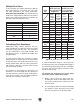
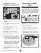
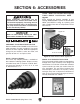
Figure 45. Additional factors affecting static
pressure.
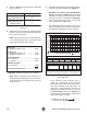
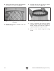
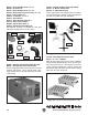
Figure 46. Totaling static pressure numbers.
Main Line
6" Rigid Duct (0.037) at 20' ................ 0.740
Branch Line
4" Rigid Duct (0.075) at 10' ................ 0.750
4" Flexible Duct (0.28) at 5' ................ 1.400
Elbows/Branches
6" 45˚ Y-Branch ................................ 0.329
4" 45˚ Elbow ........................................ 0.225
Additional Factors
Seasoned Filter ................................ 1.000
Total Static Pressure Loss ................ 4.444
Additional Factors Static Pressure
Seasoned (well used)
Dust Collection Filter
1"
Entry Loss at Large
Machine Hood
2"
4. Total your list as shown in the example below
to come up with your overall static pressure
loss number for that line.
Note:
Always account for a seasoned filter,
so you don't end up with a system that only
works right when the filter is clean.
Note: When calculating static pressure loss
to determine if multiple lines can be left open
at the same time, only include the main line
numbers once.
3. Add the additional factors from the following
table to your list.
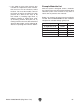
5. Compare the total static pressure loss for that
line to the closest CFM given in Figure 47.
Example: The G0703/G0703P Performance
Curve is illustrated in Figure 47. Find 4.8 on
the Static Pressure axis (the amount of total
static pressure loss calculated in Figure 28),
then refer to the closest value on the CFM
axis—approximately 708 CFM.
The 708 CFM for the static pressure loss of
the line connected to the router is well above
the 220 CFM requirement of that machine.
— If the CFM for static pressure loss is
above the requirement of the machine
connected to the end of that branch line,
then dust collection will most likely be
successful. Congratulations! You've just
designed your own dust system. Refer to
the Accessories section on Page 37 to
start buying the components necessary to
make your system a reality.
The airflow test probe is located 1.5x duct diameter upstream from
the air inlet. Test pipe length is a minimum of 10x duct diameter.
G0703/G0703P Performance Curve
1000
900
800
700
600
500
400
300
200
100
0
0.0 1.0 2.0 3.0 4.0 5.0 6.0 7.0 8.0 9.0 10.0 11.0
CFM
STATIC PRESSURE (Inch/H2O)
1.5 HP DUST COLLECTOR PERFORMANCE RESULTS
Max CFM Max SP HP Volts Inlet Impeller
775 10 1-1/2 HP 110/220V 6" 13
1
⁄2"
Restrictor Plate (Inch) Dia. 6"
Dia. 5"
Dia. 4"
Dia. 3" Dia. 2"
Static Pressure (Inch/
H2O)
1.8 3.4 4.8 7.6 9.6
CFM 775 742 708 448 316
Figure 47. G0703/G0703P performance curve
table and data.
Performance curve